Rockwell Automation Publication MOTION-RM003I-EN-P - February 2018 363
Homing Sequence Types Description
Active Home to Torque
The Home to Torque sequence is applicable when a hard stop is used to establish the
home position, as is a common practice for a linear actuator. The occurrence of the hard
stop is detected by the drive when the output torque to the motor reaches or exceeds
the Home Torque Threshold for the specified Home Torque Time. Since the Home to
Torque sequence relies on the mechanical end of travel for operation, Unidirectional
homing will not be possible so only Forward Bidirectional and Reverse Bidirectional are
allowed
. A delay filter is implemented in the drive to reduce any false/nuisance triggers
when there is a spike in the torque feedback upon enabling or jobbing the motor under
the load.
At the start of the Home to Torque sequences, the controller overrides the Torque Limit
Positive/Negative attribute values in the drive with the Home Torque Level value and
overrides the Position and Velocity Error Tolerances, saving the original values. The
drive then begins monitoring the torque reference signal, waiting for it to exceed the
Home Torque Threshold. The torque level must exceed the Home Torque Threshold for
an interval given by Home Torque Time to avoid false/nuisance trips due to the torque
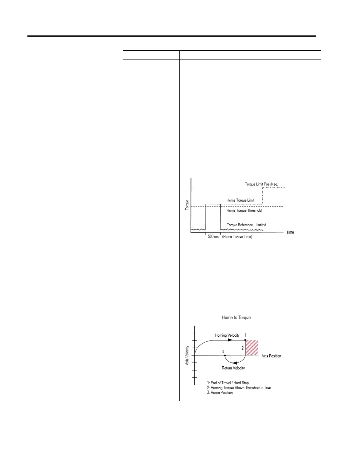
disturbances that can occur while moving the motor under load. The following timing
diagram depicts the Torque Limit adjustments, Home Torque Limit, and Home Torque
Threshold behavior during the Home to Torque sequence:
The Home to Torque sequence is similar to Home to Switch, with the exception that the
torque level is used instead of the home switch input. When this sequence is
performed, the axis moves in the specified Home Direction at the specified Home Speed
and Home Acceleration until a hard stop is detected, such as when motor torque has
exceeded the Home Torque Threshold for a period equal to Home Torque Time. At this
point, Home Position is calculated. The axis then decelerates to a stop at the specified
Home Deceleration. If Home Offset is non-zero and would not place the Home Position
of the axis further into the har
d stop, the axis moves to the Home Position at the Home
Return Speed and Home Acceleration and Home Deceleration using a trapezoidal move
profile. Finally, the controller restores overridden drive attributes to their saved original
values. Axis behavior for this homing sequence is depicted in the following diagram:

 Loading...


