364 Rockwell Automation Publication MOTION-RM003I-EN-P - February 2018
Homing Sequence Types Description
Active Home to Torque then
Marker
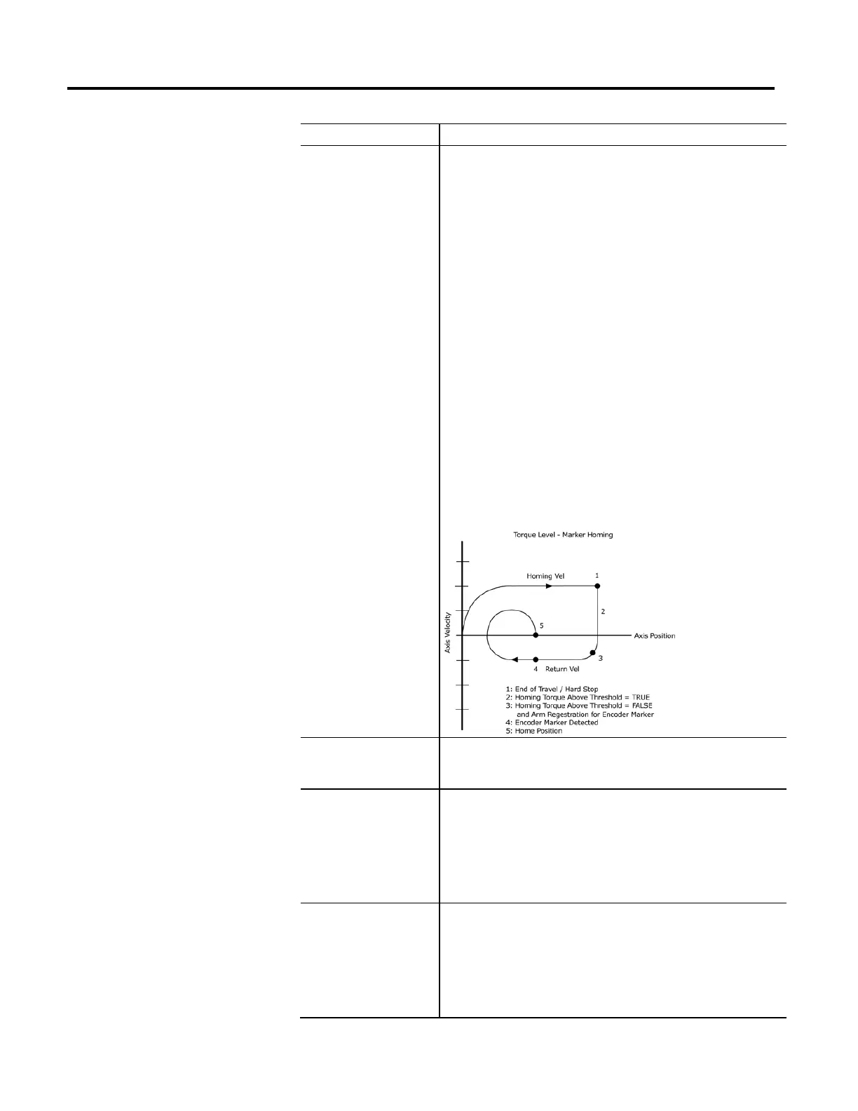
Like the Home to Torque sequence, the Home to Torque then Marker sequence is
applicable when a hard stop is used as the home position, as is common for a linear
actuator, and the feedback device is equipped with an encoder marker signal. The
occurrence of the hard stop is detected when the commanded torque applied to the
motor reaches or exceeds the user specified torque level. Since the Home to Torque
sequence relies on the mechanical end of travel for operation, Uni-directional homing
will not be possible so only Forward Bi-directional and Reverse Bi-directional are
allowed. A delay filter is implemented in the drive to reduce any false/nuisance triggers
when there is a spike in the torque feedback upon enabling or jogging the motor under
load.
By including the encoder marker in the homing sequence this is the most precise
homing operation available for torque level based homing. When this sequence is
performed
, the axis moves in the specified Home Direction at the specified Home Speed
and Home Acceleration until a hard stop is detected, such as when the Home Torque
Threshold is exceeded for a period equal to Home Torque Time. The axis then reverses
direction, f
irst decelerating at the Home Deceleration rate, then moving away from the
hard stop using the Home Acceleration to reach the Home Return Speed, until the first
encoder marker is detected. Once the marker has been detected, the Home Position is
calculated. The axis then decelerates to a stop at the specified Home Deceleration and
the controller restores overridden drive attributes to their saved original values. If the
calculated Home Position is not beyond the hard stop, the axis moves to the Home
Position at the Home Return Speed and Home Acceleration and Home Deceleration
using a trapezoidal move profile. Axis behavior for this homing sequence is depicted in
the following diagram:
Passive Immediate Home
This is the simplest passive homing sequence type. When this sequence is performed,
the controller immediately assigns the Home Position to the current axis actual
position. This homing sequence produces no axis motion.
Passive Home with Switch
This passive homing sequence is useful when an encoder marker is not available or a
proximity switch is being used.
When this sequence is performed in the Passive Homing Mode, an external agent
moves the axis until the home switch is detected. The Home Position is assigned to the
axis position at the moment that the limit switch is detected. If Home Offset is
non-zero, then the Home Position will be offset from the point where the switch is
detected by this value.
Passive Home with Marker
This passive homing sequence is useful for single turn rotary and linear encoder
applications.
When this sequence is performed in the Passive Homing Mode, an external agent
moves the axis until the marker is detected. The home position is assigned to the axis
position at the precise position where the marker was detected. If Home Offset is
non-zero, then the Home Position will be offset from the point where the switch is
detected by this value.

 Loading...


