382 Rockwell Automation Publication MOTION-RM003I-EN-P - February 2018
Motion Polarity
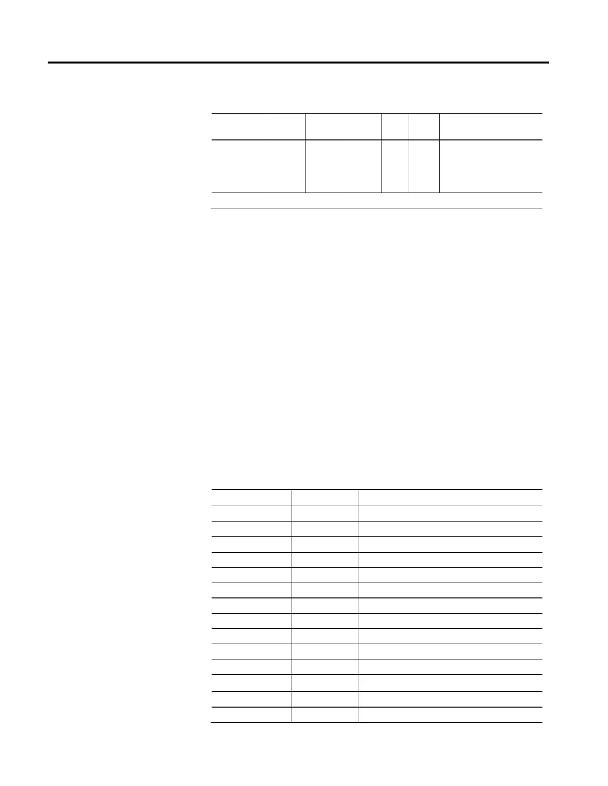
Usage Access Data
Type
Default Min Max Semantics of Values
Required - All Set/ SSV# USINT 0 0 1 Enumeration:
0 = Normal Polarity
1 = Inverted Polarity
2-255 = (Reserved)
# Indicates the attribute cannot be set while the tracking command (Tracking Command bit in CIP Axis Status is true).
When Motion Scaling Configuration is set for Drive Scaling, Motion Polarity can
be used to switch the directional sense of the motion control system. A Normal
setting leaves the sign of the motion control command and actual signal values
unchanged from their values in the drive control structure. An Inverted setting
flips the sign of the command signal values to the drive control structure and flips
the sign of the actual signal values coming from the drive control structure.
Motion Polarity can therefore be used to adjust the sense of positive direction of
the motion control system to agree with the positive direction on the machine.
When the Motion Scaling Configuration is set to Drive Scaling, the Motion
Polarity inversion is performed between the CIP Motion Connection interface
and the drive control structure. When the Motion Scaling Configuration is set to
Controller Scaling, the Motion Polarity inversion is performed exclusively by the
controller.
To maintain directional consistency, the signs of all Signal Attribute values read
from the drive control structure or being written to the drive control structure are
determined by Motion Polarity. A comprehensive list of these Signal Attributes
and their access rules is defined in the following table:
ID Access Rule Signal Attribute Name
1402+o Get Feedback n Position
1403+o Get Feedback n Velocity
1404+o Get Feedback n Acceleration
62 Get Registration 1 Positive Edge Position
63 Get Registration 1 Negative Edge Position
64 Get Registration 2 Positive Edge Position
65 Get Registration 2 Negative Edge Position
70 Get Home Event Position
360 Set* Controller Position Command - Integer
365 Get Fine Command Position
366 Get Fine Command Velocity
367 Get Fine Command Acceleration
370 Set Skip Speed 1
371 Set Skip Speed 2

 Loading...


