EasyManuals Logo

Allen-Bradley Kinetix 350 User Manual

Allen-Bradley Kinetix 350
162 pages
To Next Page IconTo Next Page
To Previous Page IconTo Previous Page
Page #45 background imageLoading...
Page #45 background image
Rockwell Automation Publication 2097-UM002D-EN-P - April 2017 45
Kinetix 350 Drive Connector Data Chapter 3
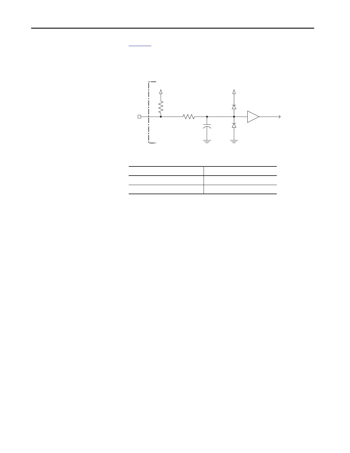
Figure 20 is the motor thermostat interface schematic. Although the
thermostat signal is shown for all feedback types, some motors do not support
this feature because it is not part of the feedback device.
Figure 20 - Motor Thermostat Interface
Table 19 - Motor Thermostat State Specifications
+5V
1 k
Ω
6.81 k
Ω
0.01 μ
F
TS
+5V
Kinetix 350 Drive
State Resistance at TS
(1)
(1) Resistance is measured between TS (MF pin 11) and ECOM (MF pin 6)
No Fault 500 Ω
Fault 10 kΩ

Table of Contents

Questions and Answers:

Question and Answer IconNeed help?

Do you have a question about the Allen-Bradley Kinetix 350 and is the answer not in the manual?

Allen-Bradley Kinetix 350 Specifications

General IconGeneral
BrandAllen-Bradley
ModelKinetix 350
CategoryServo Drives
LanguageEnglish

Related product manuals