Publication 1763-RM001B-EN-P - April 2007
Communications Instructions 377
In this example, the controller reads five elements (words) from the target
device’s (Local Node 2) CIF file, starting at word 20 (or byte 20 for
non-SLC 500 devices). The five elements are placed in the controller’s
integer file starting at word N7:0. If 15 seconds elapse before the message
completes, error bit MG11:0/ER is set, indicating that the message timed
out.
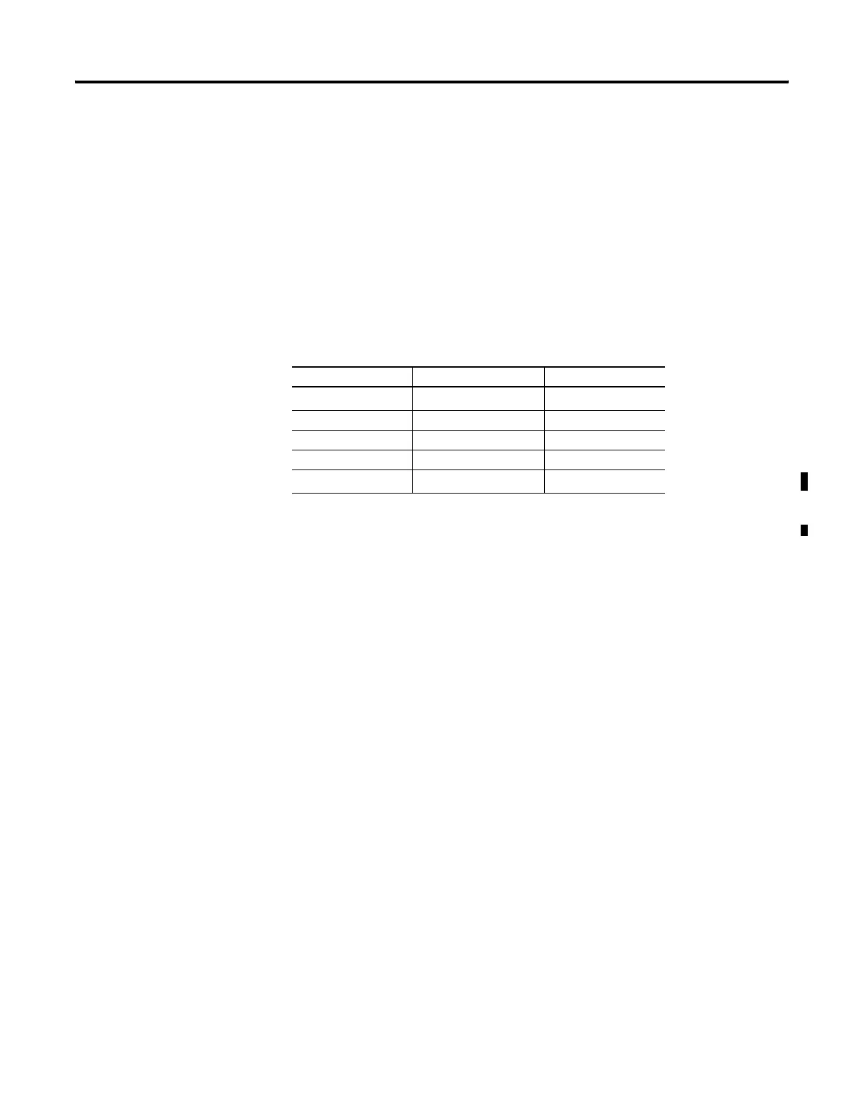
Valid File Type Combinations
Valid transfers between file types are shown below for MicroLogix
messaging:
Local Data Types Communication Type Target Data Types
O
(1)
, I
(1)
, B, N, L
(1) Output and input data types are not valid local data types for read messages.
<---> read/write 485CIF
T <---> read/write 485CIF
C <---> read/write 485CIF
R <---> read/write 485CIF
ST
(2)
(2) MicroLogix 1100 OS Series B FRN 4 or later.
<---> read/write 485CIF
efesotomasyon.com - Allen Bradley,Rockwell,plc,servo,drive

 Loading...


