Publication 1763-RM001B-EN-P - April 2007
378 Communications Instructions
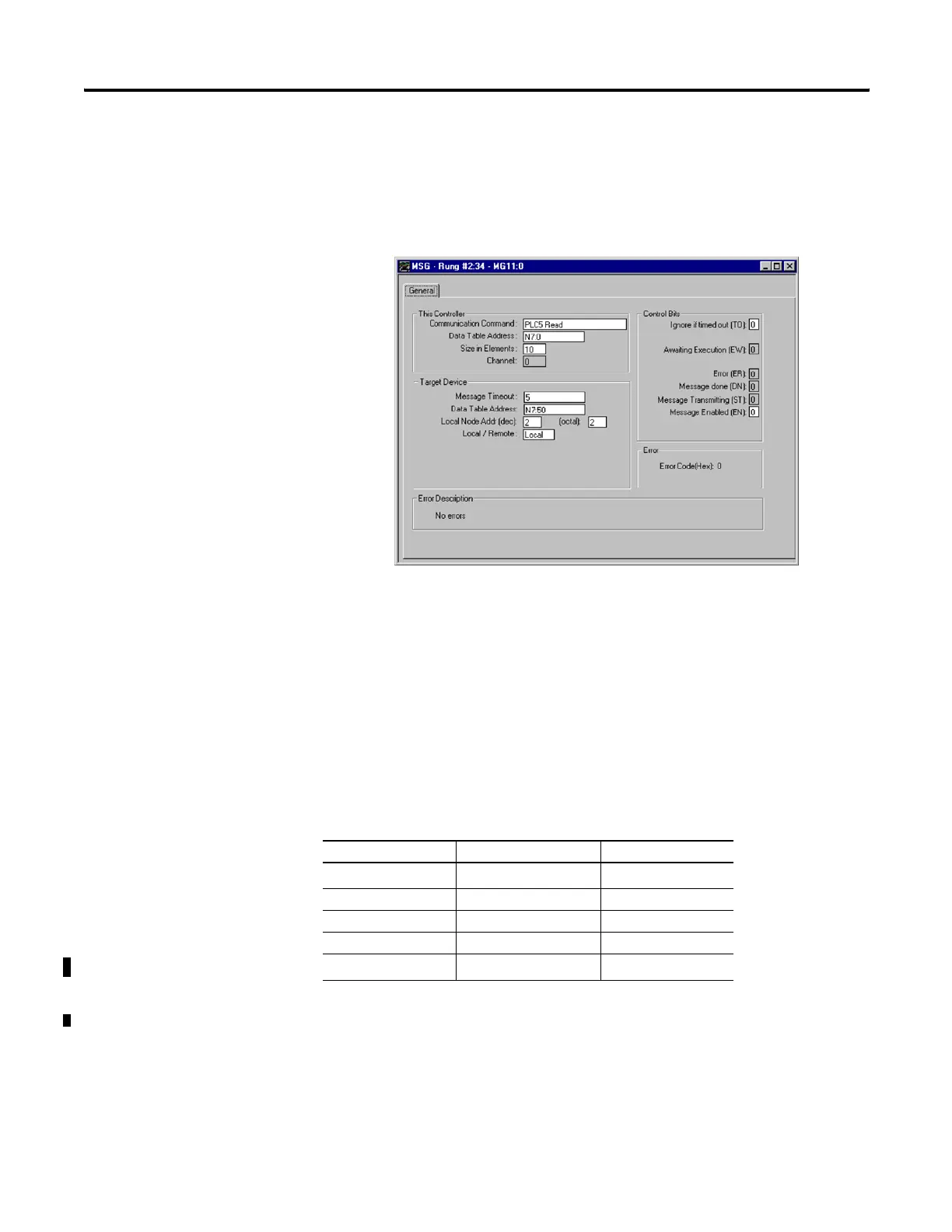
Example 3 - Local Read from a PLC-5
Message Instruction Setup
In this example, the controller reads 10 elements from the target device’s
(Local Node 2) N7 file, starting at word N7:50. The 10 words are placed in
the controller’s integer file starting at word N7:0. If five seconds elapse
before the message completes, error bit MG11:0/ER is set, indicating that
the message timed out.
Valid File Type Combinations
Valid transfers between file types are shown below for MicroLogix
messaging:
Local Data Types Communication Type Target Data Types
O
(1)
, I
(1)
, B, N, L
(1) Output and input data types are not valid local data types for read messages.
<---> read/write O, I, S, B, N, L
T <---> read/write T
C <---> read/write C
R <---> read/write R
ST
(2)
(2) MicroLogix 1100 OS Series B FRN 4 or later.
<---> read/write ST
efesotomasyon.com - Allen Bradley,Rockwell,plc,servo,drive

 Loading...


