204 Rockwell Automation Publication 7000-UM202D-EN-P - May 2018
Appendix F Line and Load Cable Sizes
6600V / 50 Hz / RPTX E325…E575,
G215, G250,
N625
70.36, 70.37 12.79 x 19.68
(325 x 500)
(1)
Two 500 MCM / phase (8 kV or 15 kV) Two 253 mm
2
/ phase (8 kV or 15 kV) 16.5 (421)
2400V / 60Hz / RP18TX
(9)
46…430 70.8 9.79 x 10.97
(249 x 279)
(1)
Two 500 MCM / phase (5 kV or 8 kV) Two 253 mm
2
/ phase (5 kV or 8 kV) 16.4 (415)
3300V / 50Hz / RP18TX
(9)
46…430 70.9 9.79 x 10.97
(249 x 279)
(1)
Two 500 MCM / phase (5 kV or 8 kV) Two 253 mm
2
/ phase (5 kV or 8 kV) 16.4 (415)
4160V / 50Hz / RP18TX
(9)
46…430 70.9, 70.18 9.79 x 10.97
(249 x 279)
(1)
Two 500 MCM / phase (5 kV or 8 kV) Two 253 mm
2
/ phase (5 kV or 8 kV) 16.4 (415)
4160V / 60Hz / RP18TX
(9)
46…430 70.8, 70.9 9.79 x 10.97
(249 x 279)
(1)
Two 500 MCM / phase (5 kV or 8 kV) Two 253 mm
2
/ phase (5 kV or 8 kV) 16.4 (415)
6600V / 50Hz / RP18TX
(9)
40…215 70.9 9.79 x 10.97
(249 x 279)
(1)
Two 500 MCM / phase (8 kV or 15 kV) Two 253 mm
2
/ phase (8 kV or 15 kV) 16.4 (415)
6600V / 50Hz / RP18TX
(9)
250…430 70.18 9.79 x 10.97
(249 x 279)
(1)
Two 500 MCM / phase (8 kV or 15 kV) Two 253 mm
2
/ phase (8 kV or 15 kV) 16.4 (415)
6600V / 60Hz / RP18TX
(9)
40…215 70.9 9.79 x 10.97
(249 x 279)
(1)
Two 500 MCM / phase (8 kV or 15 kV) Two 253 mm
2
/ phase (8 kV or 15 kV) 16.4 (415)
6600V / 60Hz / RP18TX
(9)
250…430 70.18 9.79 x 10.97
(249 x 279)
(1)
Two 500 MCM / phase (8 kV or 15 kV) Two 253 mm
2
/ phase (8 kV or 15 kV) 16.4 (415)
(1) Most PowerFlex ‘B’ frame drives have a single enclosure opening provision for both line and load cables. Most ‘B’ frames have separate opening provisions for line and load cables. All cabling capacities
shown in this table are “worst case” conditions when both line and load cabling enters and exits in the same direction.
(2) Cable sizes are based on overall dimensions of compact-stranded three-conductor shielded cable (common for industrial cable tray installations). Maximum sizing stated accounts for minimum rated
cable insulation requirements and the next higher-rated cable (for example, 8 kV is not commercially available in many areas of the world, therefore Rockwell Automation provides an 8 kV (minimum
rating) as well as a 15 kV rating, when applicable. Enclosure openings will accommodate the thicker insulation on the higher-rated cable. IEC ratings show the equivalent to the NEMA sizes. The exact
cable mm
2
size shown is not commercially available in many cases; use the next smaller standard size.
(3) Minimum cable bend radius recommendations vary by national codes, cable type, and cable size. Consult local codes for guidelines and requirements. General relationship of cable diameter to bend
radius is typically between 7…12x (for example, if the cable diameter is 1 in. [2.54 cm] the minimum bend radius could range between 7…12 in. [18.8…30.48 cm]).
(4) For minimum cable insulation requirements, see the PowerFlex 7000 user manual for your particular frame. Stated voltages are peak line-to-ground. Some cable manufacturers rate cabling based on
RMS line-to-line.
(5) Ground lug capabilities: up to ten mechanical range lugs for ground cable connections are available, typically these frames supply four. Mechanical range lugs can accommodate cable size #6-
250MCM (13.3…127 mm
2
).
(6) Maximum cable size for ‘B’ Frame (two per phase) is 500 MCM (253 mm
2
), limited by lug pad assembly size and clearance requirements.
(7) As cabling methods can vary widely, maximum cable sizes shown do not account for the size of the conduit hub. Verify size of conduit hub(s) against the load cable conduit openings shown.
(8) With a close-coupled starter.
(9)18-pulse drives have nine line-side connections (from the secondary windings of the isolation transformer) which enter the drive. Lug pads are provided for each connection. The lug pad and
enclosure opening can generally accommodate two cables per connection (18 cables total).
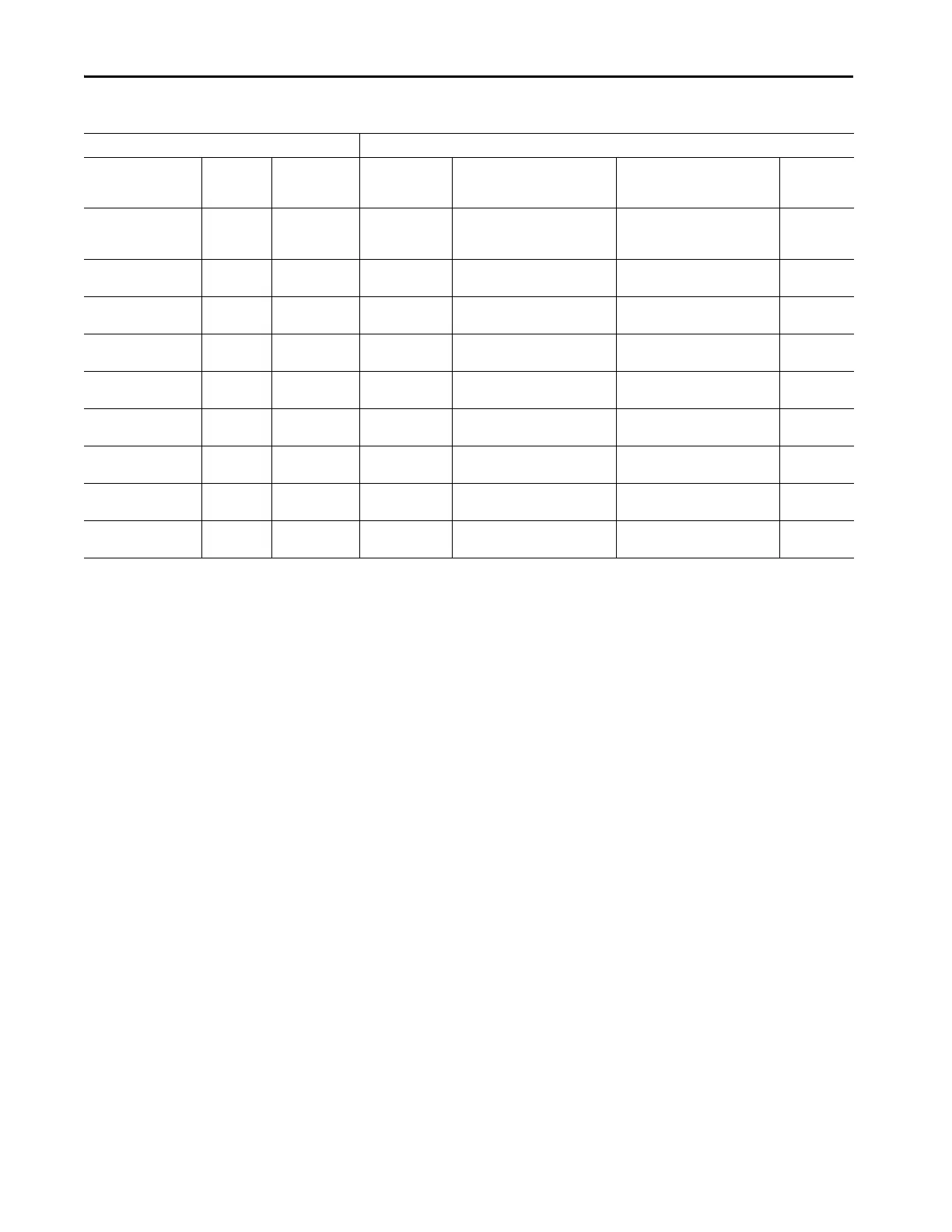
Table 19 - Maximum Load Cable Sizes
Product Output (Motor Side)
Voltage/Frequency/
Rectifier
Drive
Rating (A)
Drive Structure
Code
Load Cable
Conduit Opening
[in. (mm)]
(1)
No. and Max. Size of Outgoing
Cables (NEMA)
(2)(3)(4)(5)(6)(7)
No. and Max. Size of Outgoing
Cables (IEC)
(2)(3)(4)(5)(6)(7)
Space for
Stress Cones
[in. (mm)]

 Loading...


