Rockwell Automation Publication 7000-UM202D-EN-P - May 2018 45
Power Component Definition and Maintenance Chapter 2
Replacing the Surge Arrester
1. Isolate and lock out all power to the drive.
To access the surge arrestors in an arc resistant drive, remove the barriers
behind the swing-out LV compartment.
2. Wait a minimum of ten minutes for the drive to discharge stored energy.
3. Observe the location of the connecting leads.
4. Use proper method to ensure the leads are at ground potential. Use
temporary grounding when necessary.
5. Detach the connecting leads.
6. Loosen the bolt that attaches the surge arrester to the ground bus.
Remove the arrester. Remove temporary ground when applicable.
7. Replace the surge arrester with an equivalent one (make sure that the
voltage rating is the same).
8. Connect the leads to the surge arrester.
9. Torque the surge arrester hardware to 28 N•m (21 lb•ft).
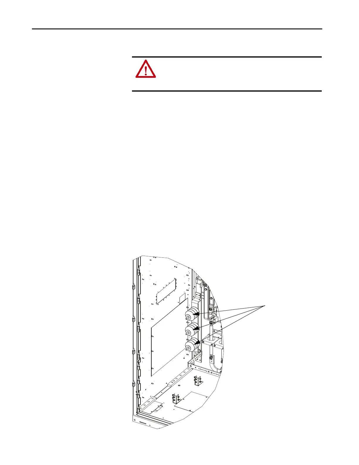
Figure 32 - Surge Arresters (Heatsink Model)
ATTENTION: To prevent electrical shock, disconnect the main power before
working on the drive. Verify that all circuits are voltage-free using a hot stick
or appropriate voltage-measuring device. Failure to do so may result in injury
or death.

 Loading...


