Publication 1747-RM001G-EN-P - November 2008
Application Specific Instructions 7-15
Read High-speed Clock and
Compute Time Difference
Overview
TDF and RHC instructions are used together. The RHC is used to record the
start and stop time of an event. The TDF is used to calculate the time
difference between the recorded start and stop times from the RHC
instruction.
RHC Instruction Operation
SLC 500 maintains a 20-bit integer free running clock. This 20-bit value
increments every 10 μs. The free running clock is non-retentive, a power cycle
resets the free running clock to 0. It is accessed using the RHC instruction.
When the RHC rung is true, the instruction moves the current value of the 10
μs free running clock into the destination address. If the destination is an
integer address, the RHC moves the first 16 least significant bits to the
destination address. If the destination is a float address, the instruction
converts the 20-bit free running clock integer value into a float and moves this
value to the destination address. Once the free running clock reaches 0x000F
FFFF (10.48575 seconds), it wraps around to 0 and continues incrementing.
TIP
The RHC instruction does have an inherent latency
due to execution time. The 20-bit float and 16-bit
integer do not have the same amount of latency. A
20-bit float destination has additional latency due to
the integer to float conversion. The accuracy of this
instruction is based on the latency of the RHC
instruction and potential hardware interrupts. See Table
7.6, “Accuracy (in counts: 1 count = 10 µs),” for more
information.
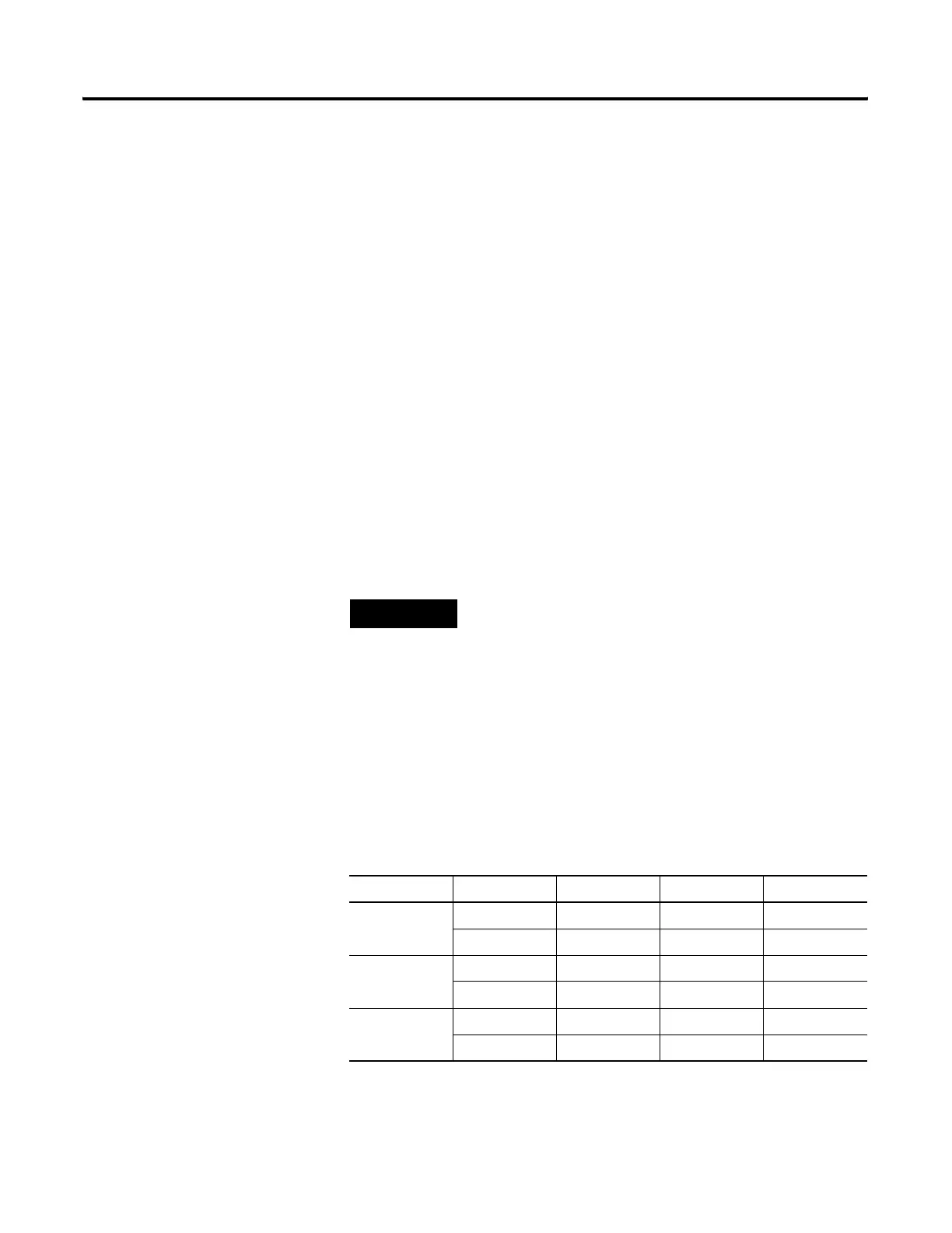
Table 7.6 Accuracy (in counts: 1 count = 10 µs)
Processor Best Case Worst Case Typical
SLC 5/05 Integer 1 26 1
Float 1 29 2
SLC 5/04 Integer 1 26 1
Float 1 29 2
SLC 5/03 Integer 1 53 2
Float 2 62 3

 Loading...


