Publication 1747-RM001G-EN-P - November 2008
SLC Communication Channels 13-63
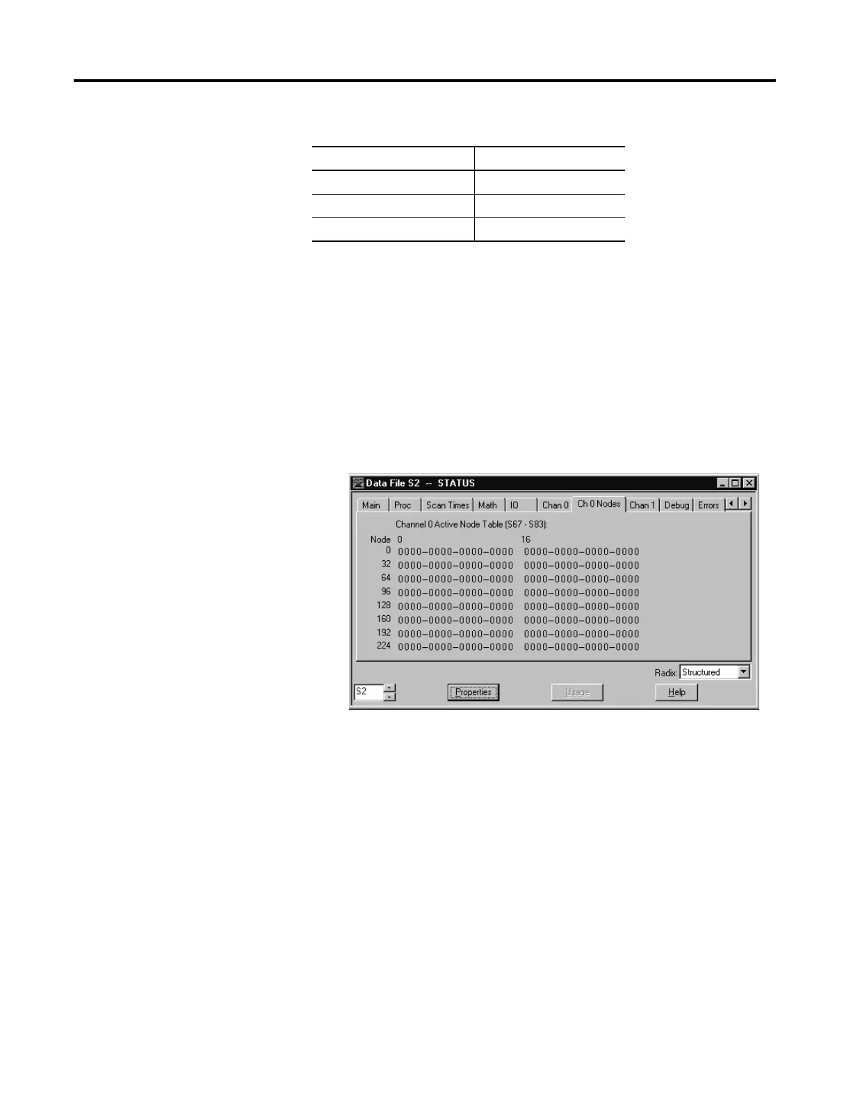
Monitor Active Stations
To see what stations are active, view the channel 0 active node table in the SLC
5/03, SLC 5/04, or SLC 5/05 processor status file (S:67/0-S:82/15). Each bit
in the file represents a station on the link. The stations are numbered in order
as a continuous bitstream file starting with the first bit in word S:67 (See Figure
13.12 below).
Figure 13.12 Example Active Node Table
At powerup or after reconfiguration, the master station assumes that all slave
stations are inactive. A station is shown active only after it responds to a poll
packet.
Configuring Channel 0 for Message-based Polling Mode DF1
Half-duplex Master
Choose DF1 half-duplex master in message-based polling mode if you want to
use MSG instructions in user programming to communicate with one station
at a time. If your application uses satellite transmission or public switched
telephone network transmission, consider choosing message-based.
Communication to a slave station can be initiated on an as-needed basis.
modem turnaround time 50
calculated ACK Timeout 304
round up to nearest 20 ms 320
Table 13.19 Sum of the Transmission Rates
Parameter Example Values (in ms)

 Loading...


