Publication 1747-RM001G-EN-P - November 2008
SLC Communication Channels 13-81
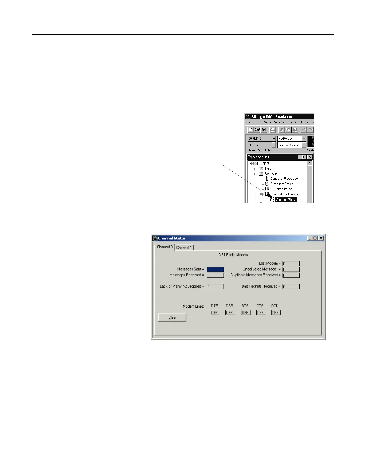
DF1 Radio Modem Channel Status
Channel Status data is stored in the diagnostic file defined on the Channel 0
Configuration screen. See Table 13.25 for information regarding the diagnostic
counter data displayed.
Double-click on the Channel Status
Icon Located beneath the
Configuration icon to bring up the
Channel Status screen.
See Table 13.25 for details
concerning the DF1 Radio
Modem Channel Status Screen.

 Loading...


