Publication 1747-RM001G-EN-P - November 2008
SLC Passthru Communications 14-9
1784-KT, -KTX(D), -PKTX(D), or –PCMK card. When RSWho is browsing
the SLC 5/04 on DH+, and channel 0 is either configured for DH-485 with
S:34/0=0 or for DF1 with S:34/5=1, then a ‘+’ sign will appear to the left of
the SLC 5/04 icon. Clicking on the ‘+’ sign will expose a DH-485 or DF1
network underneath the SLC 5/04 icon. Clicking on the ‘+’ sign to the left of
the DH-485 or DF1 network will result in RSWho browsing for nodes 0-31 on
the DH-485 network or for node 1 on the DF1 network.
Refer to the steps on page 14-13 for browsing multiple nodes when channel 0
is configured for DF1 Half-duplex Master or DF1 Radio Modem.
Creating and Filling out the Passthru Routing Table File
The SLC 5/05 processor uses a routing table to cross-reference the one-byte
addressing used by DF1 and DH-485 protocols with the four-byte IP address
needed to support Ethernet communication. The routing table is stored in a
user-selectable integer Data File and uses two word elements of the integer file
to store one IP address.
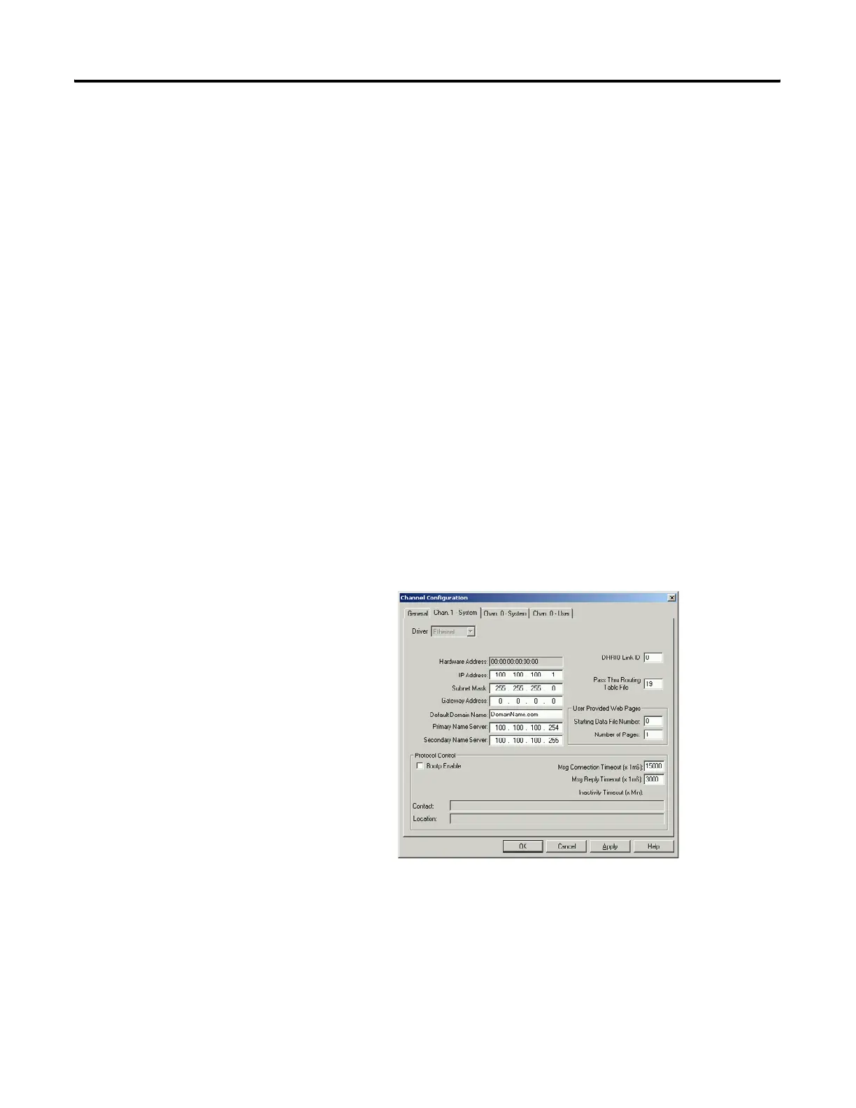
The Routing Table data file is defined in the Chan. 1 – System menu under
Channel Configurations.
The routing table file number must be between 9 and 255 (a valid data table
address). A value of zero will disable the routing table and disable passthru
functionality. The routing table file must be at least two words in length.

 Loading...


