Publication 1747-RM001G-EN-P - November 2008
Processor Files 1-5
Addressing Structure
Address bits and words using the format Tf:e.s/b.
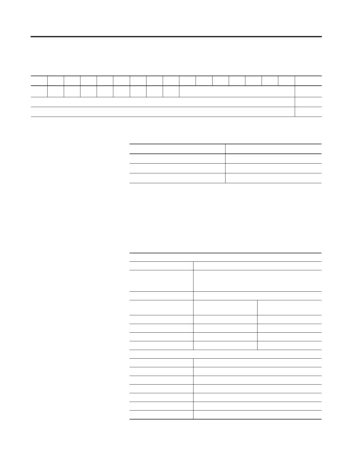
Table 1.4 Timer Control Fields
15 14 13 12 11 10 9 8 7 6 5 4 3 2 1 0 Word
EN TT DN
Internal Use
(1)
0
Preset Value (PRE) 1
Accumulator Value (ACC) 2
(1)
Bits labeled “Internal Use” are not addressable.
Table 1.5 Timer Elements
Addressable Bits Addressable Words
EN = Enable (Bit 15) PRE = Preset Value
TT = Timer Timing (Bit 14) ACC = Accumulated Value
DN = Done (Bit 13)
Table 1.6 Timer Addressing Format
Explanation
T Timer file
f File number. For SLC 500 processors the default is 4. A file
number between 9 to 255 can be used for additional
storage.
: Element delimiter
e Element number These are 3-word elements.
The range is 0 to 255.
. Word Delimiter Range 0 to 2
s Word Number
/ Bit delimiter
b Bit Number Range 0 to 15
Examples
T4:0/15 or T4:0/EN Enable bit
T4:0/14 or T4:0/TT Timer timing bit
T4:0/13 or T4:0/DN Done bit
T4:0.1 or T4:0.PRE Preset value of the timer
T4:0.2 or T4:0.ACC Accumulated value of the timer
T4:0.1/0 or T4:0.PRE/0 Bit 0 of the preset value
T4:0.2/0 or T4:0.ACC/0 Bit 0 of the accumulated value

 Loading...


