Publication 1747-RM001G-EN-P - November 2008
12-52 SLC Communication Instructions
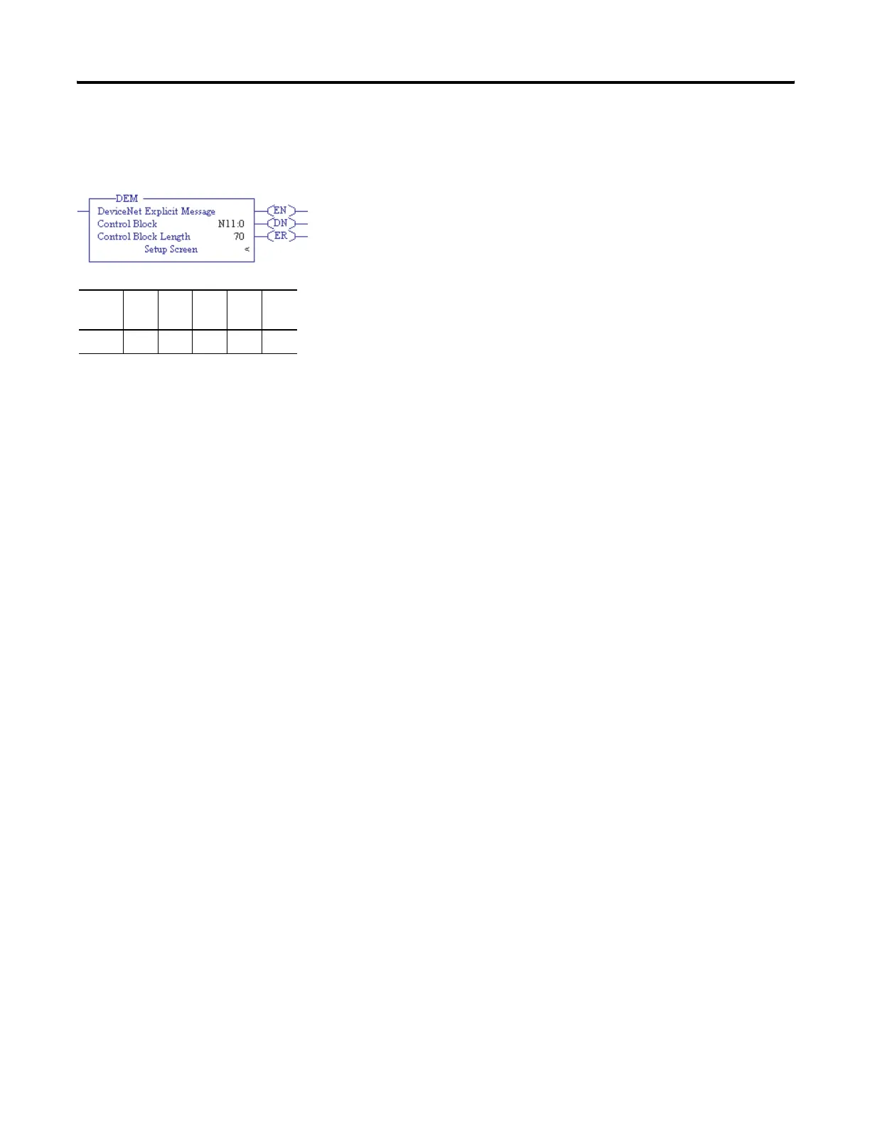
DeviceNet Explicit
Message (DEM)
This is an output instruction that lets you initiate unconnected CIP Generic
messages via a 1747-SDN DeviceNet scanner module installed in the local
chassis. These messages can be initiated to any node on the same DeviceNet
network as the 1747-SDN, as long as the node is in the scanner’s scan list. The
scanner can be in either Idle mode or Run mode. Each scanner module can
only process one DEM instruction at a time. The instruction is similar in
operation to a standard MSG instruction.
DEM Instruction Parameters
Enter the following parameters when programming this instruction:
• Control Block is an integer file address that you select. It is a block of
words, containing the status bits and other data associated with the
DEM instruction. It also contains the Send and Receive data.
• Control Block Length is a display-only field that indicates how many
integer file words are being used by the control block. For the DEM
instruction, the length is always 70 words.
DEM Instruction Setup Screen Parameters
The following sections provide parameters for the DEM instruction setup
screens.
Parameters for This Controller on the General Tab
• 1747-SDN Slot
This drop-down field lists all of the local slots that contain DeviceNet
scanner (1747-SDN) modules within the IO Configuration. Select the
slot number of the particular scanner module that this explicit message
will be initiated through.
• Size in Send Data (Bytes)
This field defines how many bytes of data are sent along with this
explicit message command. If unsure of how much data will be sent,
you may select up to the maximum size of 52 bytes when defining the
instruction, and then reduce the size later based on experience.
Fixed SLC
5/01
SLC
5/02
SLC
5/03
SLC
5/04
SLC
5/05
•••

 Loading...


