1 Publication 1747-RM001G-EN-P - November 2008
Chapter
1
Processor Files
File Structure
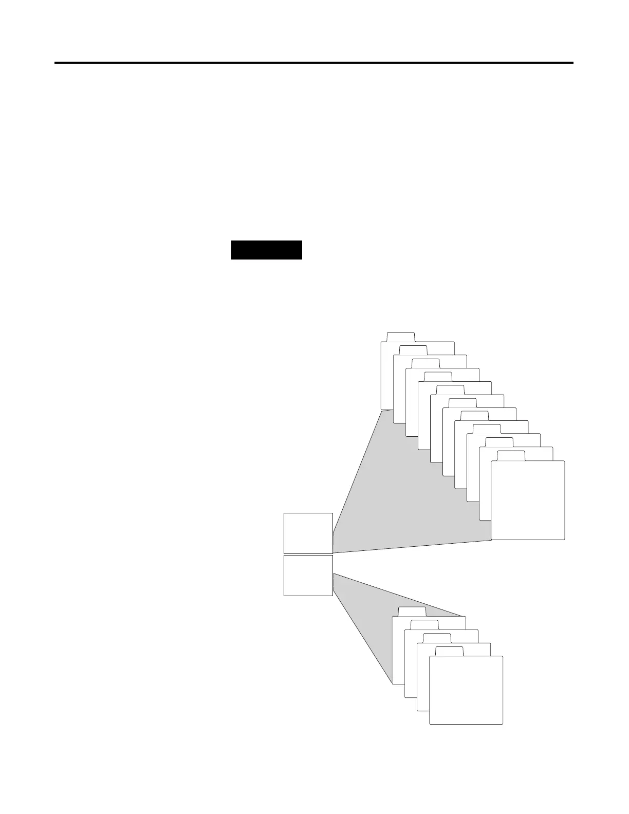
SLC 500 user memory is comprised of Data Files and Program Files.
TIP
The file types shown below for data files 3 through 8
are the default values. Files 9 to 255 can be
configured to be bit, timer, counter, control, integer,
floating point, ASCII, or String files.
Data
Files
Program
Files
0
1
2
3
5
6
4
7
9 to 255
BBit
TTimer
C Counter
RControl
N Integer
F Floating Pt.
(1)
ST String
(1)
A ASCII
(1)
Output File
Input File
Status File
Bit File
Timer File
Counter File
Control File
Integer File
0
1
System File 0
2
3 to 255
Program File 2
Program Files
3 to 255
System File 1
(1) SLC 5/03 and higher processors only.
Floating Point File
8

 Loading...


