Publication 1747-RM001G-EN-P - November 2008
1-4 Processor Files
Timer Data File (T4:)
Timer instructions use various control bits. These are 3-word elements, used
with Bit, TON, TOF and RTO instructions. Word 0 is the status word, word 1
indicates the preset value, and word 2 indicates accumulator value. This is
shown in Table 1.4.
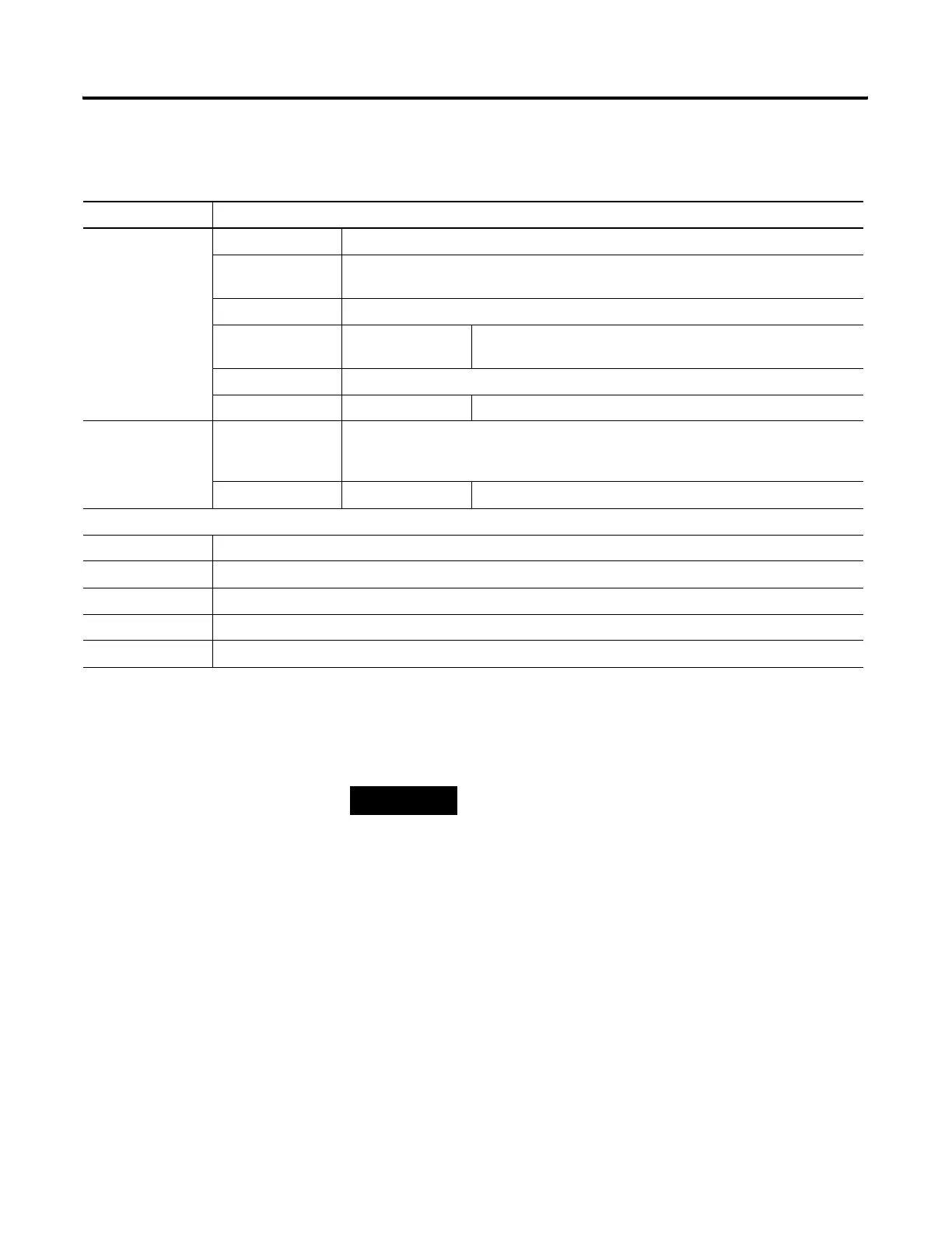
Table 1.3 Bit File Addressing Format
Format Explanation
Bf:e/b B Bit type file
f File number. Number 3 is the default file. A file number between 9-255 can be used if
additional storage is required.
: Element delimiter
e Element number Ranges from 0-255. These are 1-word elements. 16 bits per
element.
/ Bit delimiter
b Bit number Bit location within the element. Ranges from 0-15.
Bf/b B
f
/
Same as above.
Same as above.
Same as above.
b Bit number Numerical position of the bit within the file. Ranges from 0-4095.
Examples:
B3:3/14 Bit 14, element 3
B3:252/00 Bit 0, element 252
B3:9 Bit 62
B3/62 Bit 62
B3/4032 Bit 4032
TIP
Timing could be inaccurate if Jump (JMP), Label
(LBL), Jump to Subroutine (JSR), or Subroutine (SBR)
instructions skip over the rung containing a timer
instruction while the timer is timing. If the skip
duration is less than 2.5 seconds, no time will be lost;
if the skip duration exceeds 2.5 seconds, an
undetectable timing error occurs. When using
subroutines, a timer must be executed at least every
2.5 seconds to prevent a timing error.

 Loading...


