0120028-J0 Rev F
12
4� Features
4�1 Converter Modules
A module contains four isolated DC to DC converters with a common control and supervisory circuit. An internal
microcontroller monitors both the inputs and outputs of the converters, turns the converters on and off, and
generates a converter fail alarm if required. Each module output operates independently.
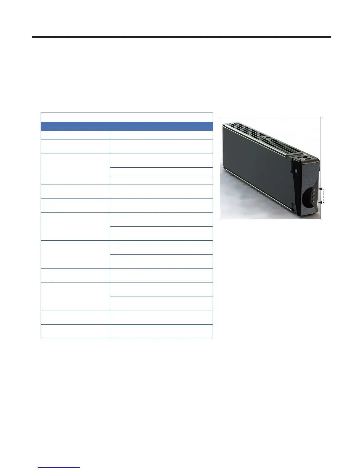
4�1�1 Status Indicators
The converter module has four LED indicators – per converter. Refer to section 7.3 for more details. The LEDs are
color-coded to indicate converter status as follows:
4 status LEDs–one per converter
Table A — Converter Status LEDs
LED State Converter Status
Green
Normal
Blinking Green
Remote shutdown enabled on
individual channel/converter
Blinking Green
(All 4 LEDs)
Remote shutdown enabled on whole
module
Shelf is not compatible with the module
Module not seated properly
Yellow (All 4 LEDs)
Recoverable:
• Ambient temperature high
Blinking Yellow (All 4
LEDs)
Input qualify not OK
Blinking Yellow
Recoverable:
• OCP/Overload
Non-recoverable:
• Converter Input Fuse fail
Red
Locked-State:
• OVP
Non-recoverable:
• Converter Output Fuse fail
Blinking Red
Non-recoverable:
• Secondary sensory fail
OFF (All 4 LEDs)
Recoverable:
• No power
Non-recoverable:
• Main Input Fuse cut-off
Chasing Green Pattern
(All 4 LEDs)
Non-recoverable:
• Group reset function not working
Chasing Red/Green
Pattern (All 4 LEDs)
Locate feature enabled
4�1� 2 Converter Alarms
Two (converter fail) outputs are present at the card edge connector. Alarms are activated after a one second delay
for the following conditions:
• Internal regulation fails
• Output voltage <45V
• Over voltage protection (OVP) operation
• Secondary current sensor fail
• Input fuse or output fuse fail