23
0120028-J0 Rev F
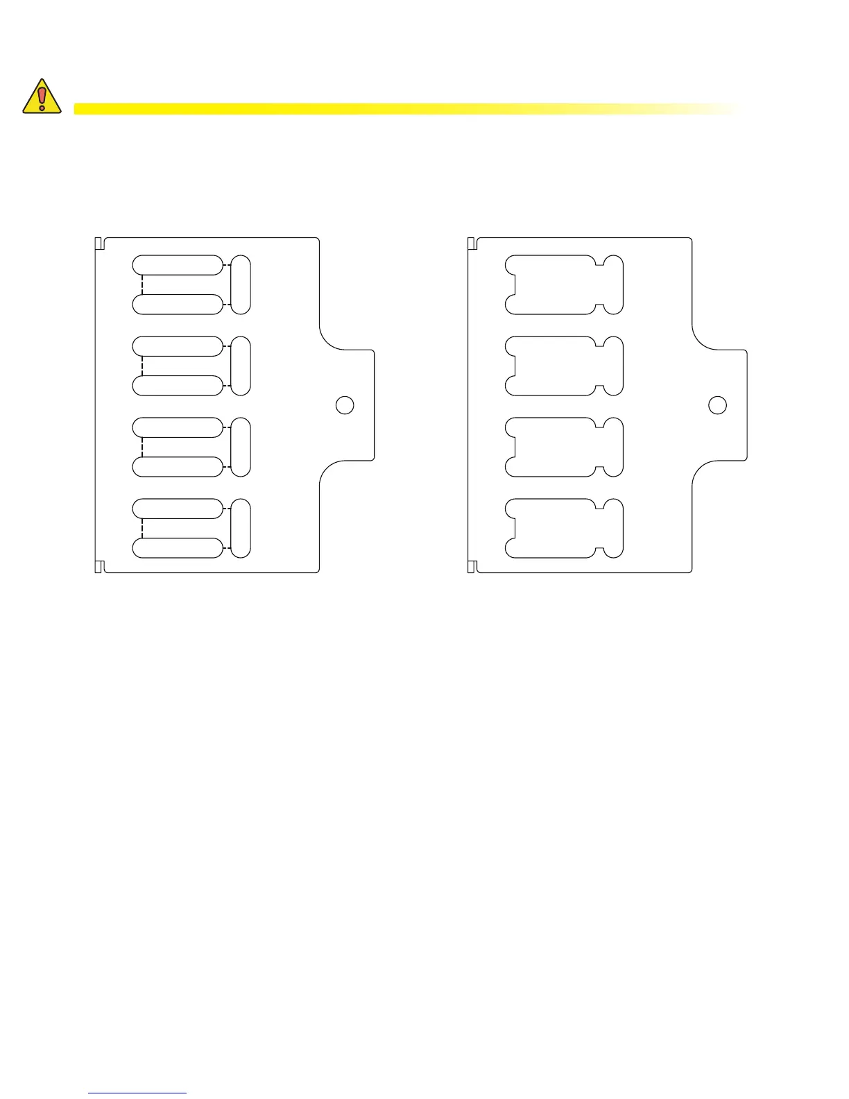
4. Trim the side cover between the slots as required for the cables to fit through. See Figure 12 and Figure 13.
Figure 12 — Cut lines for cable input Figure 13 — Cut lines for cable input
5. Push the cables through the newly created openings and install them on the input terminals.
6. For reinstallation, the front flap of the front cover should be installed before the side cover (the side cover
locks the front cover in place).
7. When reinstalling the side cover the black formex separators (shown in Figure 11), should poke through the
new openings (Figure 13) in the cover along with the cables.
CAUTION!
The cut out guidelines illustrated in Figures 12 and 13 are for reference purposes only,
the actual trimming should be performed in a manner to assure minimal clearance
around the incoming cables relative to their specic size. Maintaining this minimal
clearance (i.e. .25 inch), will prevent accidental contact with the supply voltages and as-
sure compliance with user accessibility requirements.