27
0120028-J0 Rev F
6�6 Wiring the Alarm Relays
6�6�1 Converter Shelf
Two Form C relay contacts are available for Major and Minor alarms.
Connect the relays (located on the side of the controller-side of the
shelf) to the local alarm-sending unit using wire gauges from #28 to
#16 AWG (0.08 to 1.31 mm
2
). The NO/C/NC positions for each alarm
are shown in Figure 21.
Outputs from the alarm relays can be ganged to produce one alarm at
the alarm-sending unit.
Note: Terminal blocks for major and minor alarms use molex
connector 39-01-4031. It mates with Alpha alarm mini-
fit JR. receptacle 5566-03A3-210. Kit #8700649-001 is
available with 1 connector.
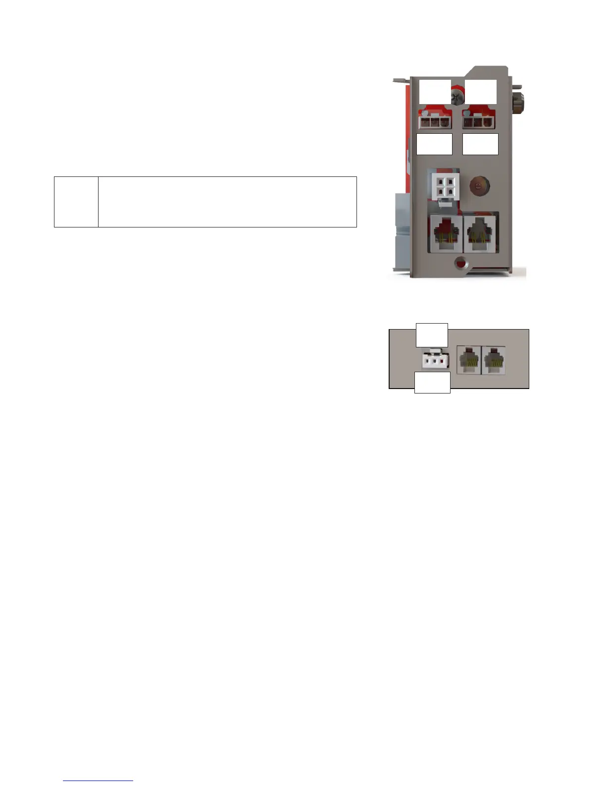
Figure 21 — Converter shelf alarm relays
NO
C
NC
Major
Alarm
Figure 22 — Fan tray alarm relay
6�6�2 Optional Fan Tray
Use wire gauges from #28 to #16 AWG (0.08 to 1.31 mm
2
)
The NO/C/NC positions for each alarm are shown in Figure
22. Failure of a fan generates a Major alarm.
The form C relay, on the side of the fan tray, can also be
connected to the local alarm-sending unit.
Outputs from the alarm relays can be ganged to produce
one alarm at the alarm-sending unit.
NO
C
NC
NO
C
NC
Major
Alarm
Minor
Alarm