0120028-J0 Rev F
24
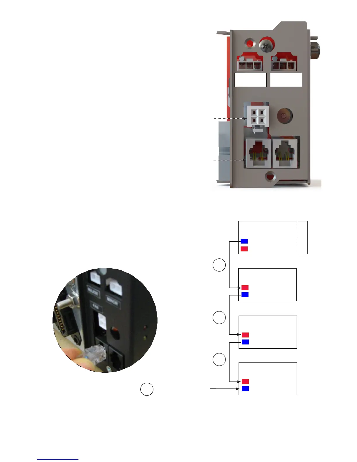
Figure 14 — CAN and fan connections on the shelf interface panel
6�5�4 Making CAN Bus Connections
Each module communicates with the CXCI+ using CAN pro-
tocol. The modules report alarms, converter output voltages,
ambient temperature and the location of the module within a
cabinet.
Figure 15 — CAN Bus cabling
Fan power connector
CAN connectors
Major alarm
relay
Minor alarm
relay
1
2
4
3
CAN OUT
CAN IN
Converter shelf #2
CAN OUT terminator
CAN OUT
CAN IN
CXCI+
Converter shelf #1
CAN OUT
CAN IN
Converter shelf #3
CAN OUT
CAN IN
Fan tray
1. Connect the daisy-chained CAN bus cable from the top shelf to
the last shelf or the fan tray. Figure 15 shows the wiring for three
shelves and a fan tray.
2. Insert the CAN terminator (P/N 5450228-001) in the last CAN
OUT location.
Figure 16 — CAN OUT terminator