0120028-J0 Rev F
14
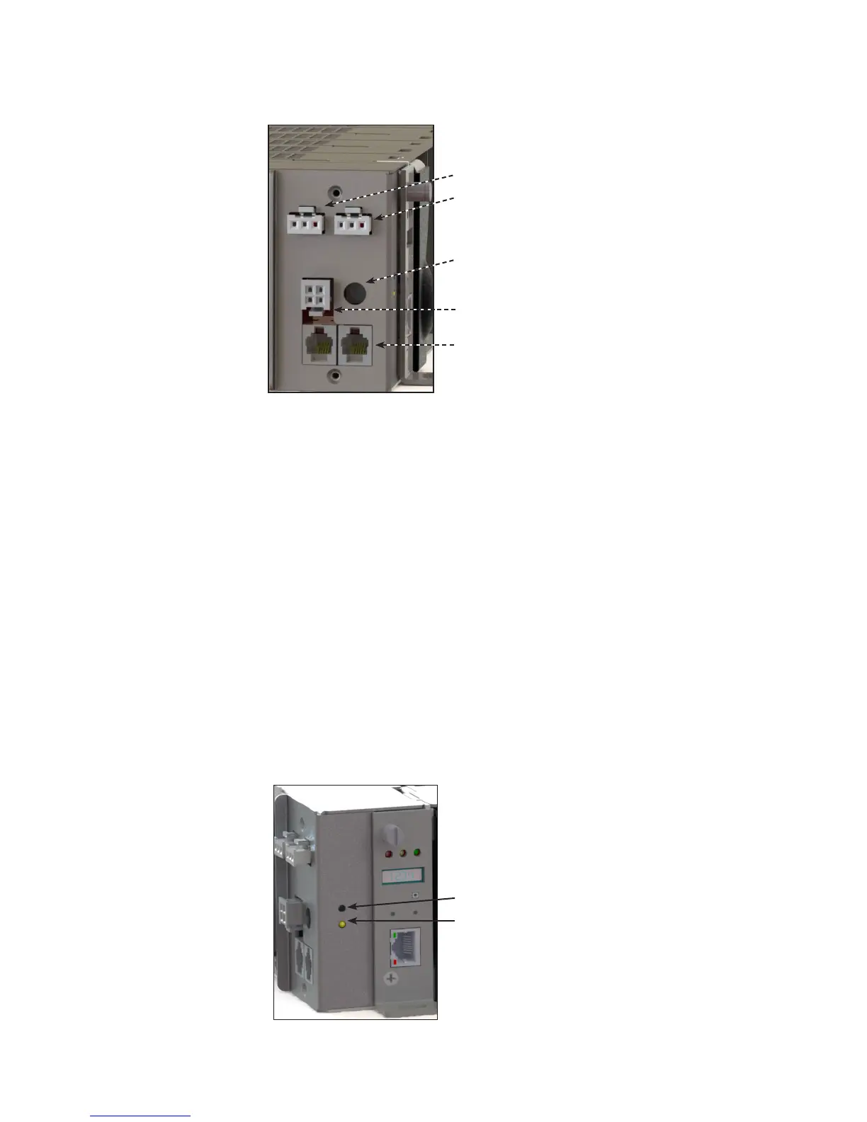
Figure 3 — Shelf connections
4�3 Shelf Connections and Indicators
Connections to alarms as well as load connections are conveniently located on the side of each shelf.
Fan power connector
Major alarm relay
Minor alarm relay
CAN connectors
Shelf ID rotary switch
4�3�1 Alarm Relays (Form C Contacts)
The converter shelf has an interface panel with terminal blocks for Major and Minor alarm outputs (Form C contacts),
which are controlled by the CXCI+. The Major alarm relay is designed as a “fail safe” to ensure the alarm is registered
when power is removed.
Major Alarm
The Major alarm relay de-energizes under any one of the following conditions:
• Two or more outputs have failed within a shelf
• One -48V input below 40V
• One -48V input is greater than -60V
Minor Alarm
The Minor alarm relay is energized under any one of the following conditions:
• Single output failed within a shelf
• Internal ambient temperature out of range
Alarm LEDs
There are two LEDs—one red and one yellow, on the front of the interface panel, that indicate shelf alarm status, see
the following figure.
Red
Major alarm
Yellow
Minor alarm
Off
OK, no alarms
Figure 4 — Shelf alarm LEDs