0120028-J0 Rev F
20
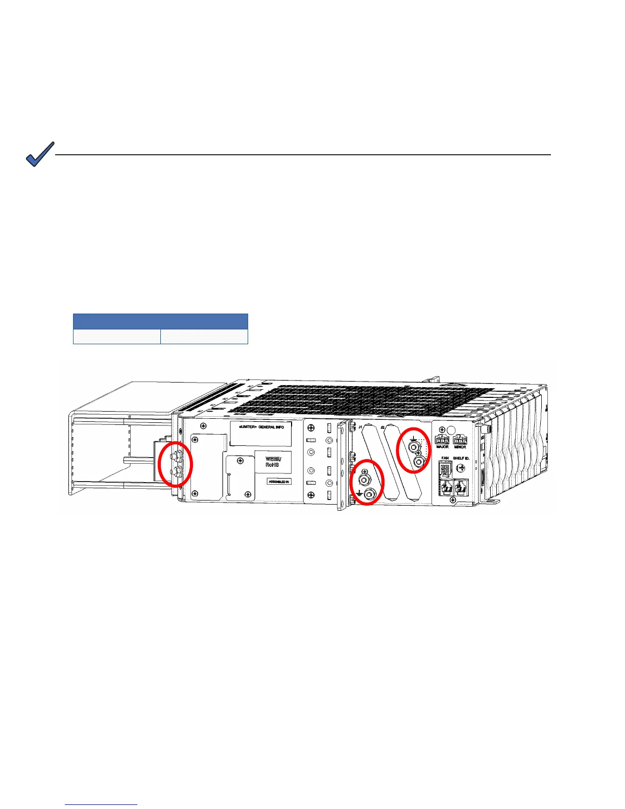
Figure 8 — Locations for protective earthing terminals for chassis ground (eLimiter+ side view)
6�5 Input and Output Wiring
This power system is suitable for installation as part of a Common Bonding Network (CBN) and is intended to be
used in a DC-I configuration (isolated from frame ground).
This system is intended to be used with a -48Vdc rectifier/ battery system at the input, and surge protectors and line
terminators at the output.
6�5�1 Wiring Chassis Ground
NOTE:
Ground connections are bright electro tin plated class B as per ASTM B545-97 Class B.
No antioxidant is required before crimp connections are made.
Protective earthing terminals are provided for chassis ground—two pair at the side and one pair at the rear (Figure 8).
1. Connect the power system chassis to the building master ground bus (MGB). This connection is necessary for
personnel safety and to meet many telco-grounding requirements.
2. Use minimum #6 AWG (16mm) copper wire and standard 2-hole crimp lugs for #10 studs on 5/8" centers.
3. Secure the lugs with #10-32 serrated flanged nuts (supplied) to provide the anti-rotation necessary for primary
ground connections.
Recommended torque values
#10-32 45 in-lbs.