0120028-J0 Rev F
48
4. Remove the two screws and then slowly slide the entire interface bracket out for about 2 inches. At this
distance, the ribbon cable (not shown) should still maintain some slack.
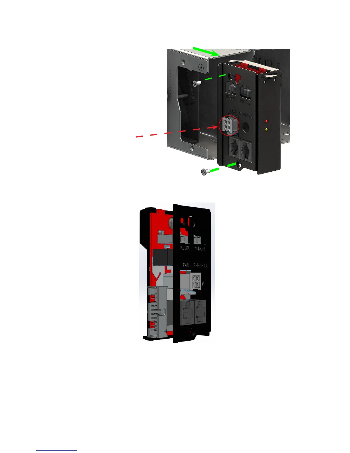
5. Carefully disconnect the female end of the 20-pin ribbon cable from the male end socket (shown below).
The 20-pin connectors are directional, so you can only place it in one way due to the notch on the male-end
and tab design on the female end.
6. Insert the new interface Kit 0380148-001 and reverse the instructions.
• Make sure that the ribbon cable maintains some slack during the pin connection.
7. Re-insert the controller (if applicable).
Outlined is part of the fan tray power
cable (for reference ) it may or may
not to be connected depending on the
required system setup .