Software Setup
NHA80945 04/2017 51
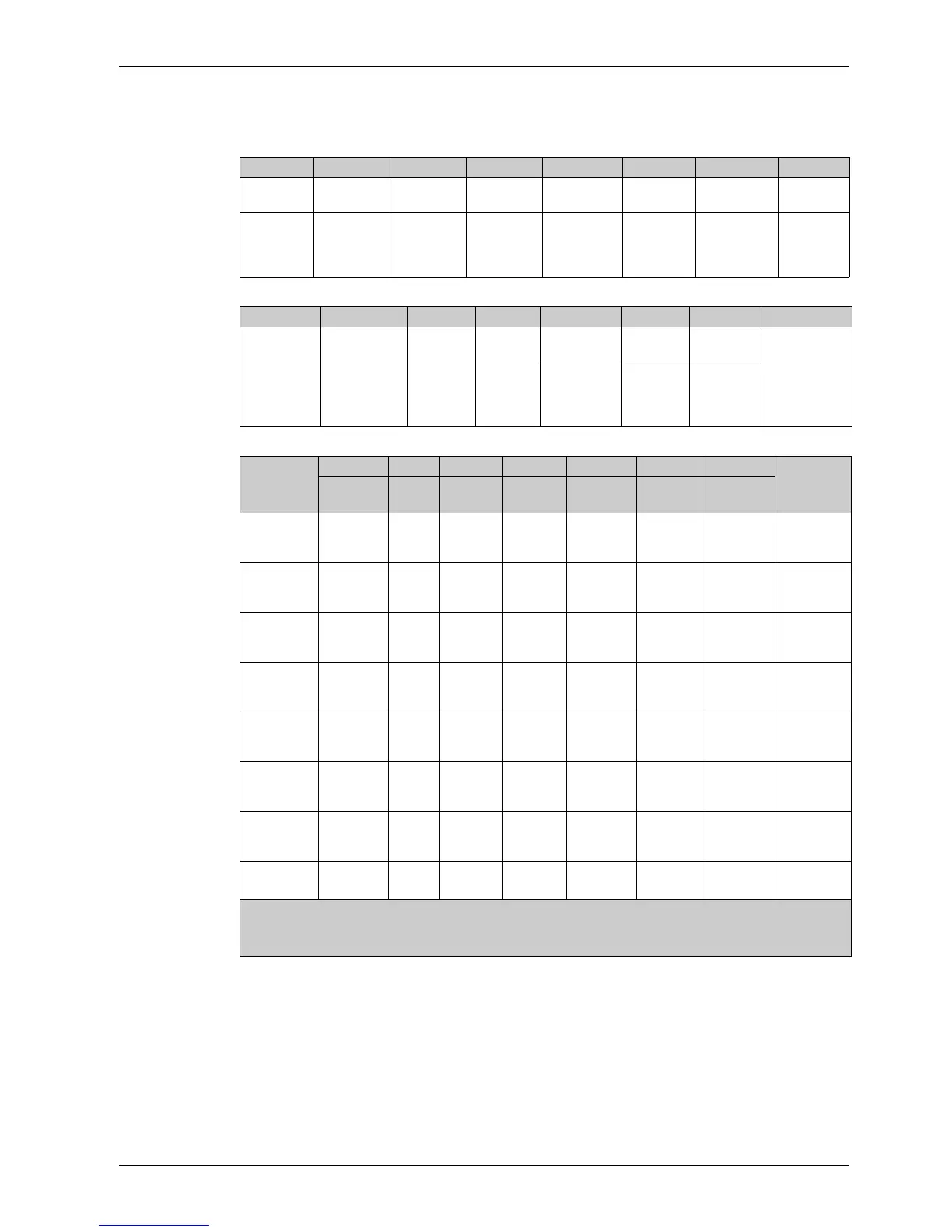
[CIA402 State Reg] EtA
Bit Mapping of the Status Word
Bit 7 Bit 6 Bit 5 Bit 4 Bit 3 Bit 2 Bit 1 Bit 0
Warning Switch on
disabled
Quick stop Voltage
enabled
Fault Operation
enabled
Switched on Ready to
switch on
A warning is
active
Power stage
supply
disabled
0 = Quick
stop is active
Power stage
supply
present
Error
detected
Running Ready 1 = Awaiting
power
Stage
supply
Bit 15 Bit 14 Bit 13 Bit 12 Bit 11 Bit 10 Bit 9 Bit 8
Manufacturer
-specific
Direction of
rotation
Manufacturer-
specific Stop
via STOP key
Reserved
(=0)
Reserved
(=0)
Internal limit
active
Target
reached
Remote Reserved (=0)
Reference
value outside
limits
Reference
value
reached
Command
or reference
value via
fieldbus
Operating
State
Bit 6 Bit 5 Bit 4 Bit 3 Bit 2 Bit 1 Bit 0 ETA Masked
by 006F H
(1)
Switch On
Disabled
Quick
Stop
Voltage
Enabled
Fault Operation
Enabled
Switched
On
Ready to
Switch On
1 -Not
ready to
switch on
0XX0000−
2 -Switch
on
disabled
1 X X 0 0 0 0 0040 hex
3 -Ready
to switch
on
0 1 X 0 0 0 1 0021 hex
4 -
Switched
on
0 1 1 0 0 1 1 0023 hex
5 -
Operation
enabled
0 1 1 0 1 1 1 0027 hex
6 -Quick
stop
active
0 0 1 0 1 1 1 0007 hex
7 -Fault
reaction
active
0 X X 1 1 1 1 002F hex
8 -Fault
0XX1000
0008 hex
(2)
..
.0028 hex
(1)
This mask can be used by the PLC program to test the diagram state.
(2)
detected error following operating state 6 - Quick stop active.
X: In this state, the value of the bit can be 0 or 1.