Hardware Setup
32
NHA80945 04/2017
Cable Specification and Maximum Bus Length
The following table describes the maximum length:
The reference potential CAN_GND and the shield connection (connector housing) are galvanically
isolated.
Keep the galvanic isolation in order to avoid ground loops via the CAN bus.
Use equipotential bonding conductors.
Use pre-assembled cables to reduce wiring errors.
Verify that wiring, cables, and connected interfaces meet the PELV requirements.
Terminating Resistor
Terminating resistors must be placed on both ends of a CAN bus line. A 120 Ohm terminating resistor
between CAN_L and CAN_H is used for this purpose.
Cable Routing Practices
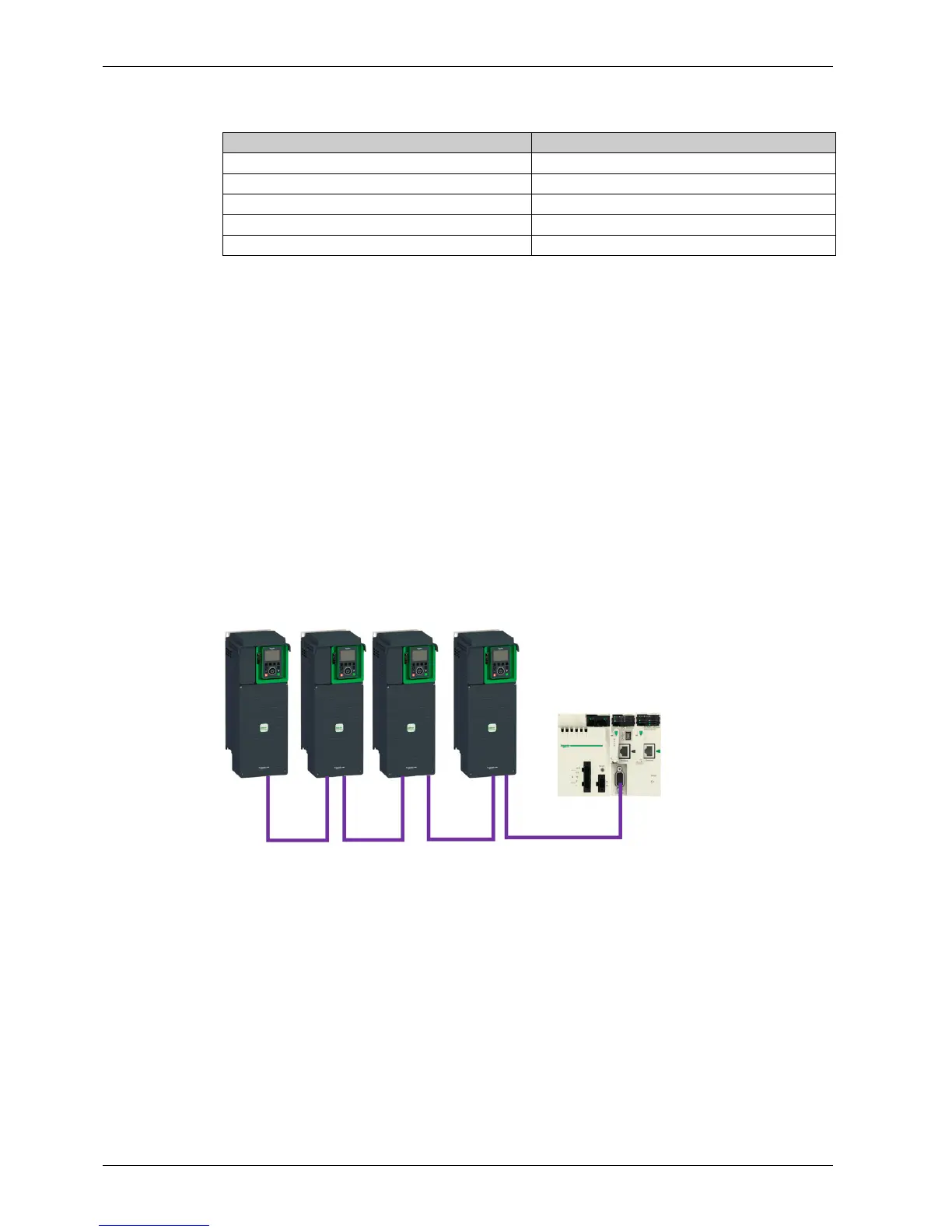
Installation Topology
The following image shows the connection of multiple drives equipped with VW3A3608 CANopen
modules.
Baud rate KBit/s Maximum bus length m (ft)
50 1000 (3280)
125 500 (1640)
250 250 (820)
500 100 (328)
1000 20 (65)