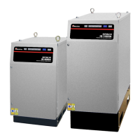
IS-200A
Contents
Thank you for purchasing our DC Inverter Welding Power Supply IS-200A.
This operation manual describes its method of operation and precautions for use.
Read this operation manual carefully prior to use. Store appropriately for ready reference.
Contents
1. Special Notes
(1) Safety Precautions ································································· 1-1
(2) Precautions for Handling ························································· 1-4
(3) On Disposal ········································································· 1-5
(4) Warning Label for Safety ························································· 1-5
2. Features ·················································································· 2-1
3. Name and Functions of Each Section
(1) Front Panel ·········································································· 3-1
(2) Rear Panel ··········································································· 3-3
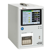
(3) MA-627A (Sold Separately) ····················································· 3-4
4. How to Operate Screens
(1) MENU Screen ······································································· 4-1
(2) POWER SUPPLY STATE Screen ·············································· 4-1
(3) SCHEDULE Screen ······························································· 4-3
(4) MONITOR Screen ································································· 4-10
(5) MONITOR SET Screen ··························································· 4-12
(6) COPY SETUP DATA Screen ···················································· 4-13
(7) MODE SELECT Screen ·························································· 4-15
(8) MONITOR MODE Screen ······················································· 4-24
(9) STEPPER COUNT Screen ······················································ 4-26
(10) I/O CHECK Screen ······························································ 4-27
(11) RESET TO DEFAULT Screen ················································· 4-28
(12) PROGRAM PROTECT MODE Screen ····································· 4-28
(13) OVER WRITE / DOWN LOAD Screen ······································ 4-29
5. Connection Procedures
(1) Basic Configurations ······························································ 5-1
(2) Connecting ··········································································· 5-2
6. Interface
(1) Connection Diagram for External Input/Output Signals ·················· 6-1
(2) Description of External I/O Signals ············································ 6-3
(3) Connection of Input Signals ····················································· 6-6
7. Basic Operation ········································································ 7-1
8. Timing Chart
(1) Basic Sequence ···································································· 8-1
(2) Detailed Description of Welding Current and Sequence
in the Event of an Error ··························································· 8-2