IS-200A
4. How to Operate Screens
4-10
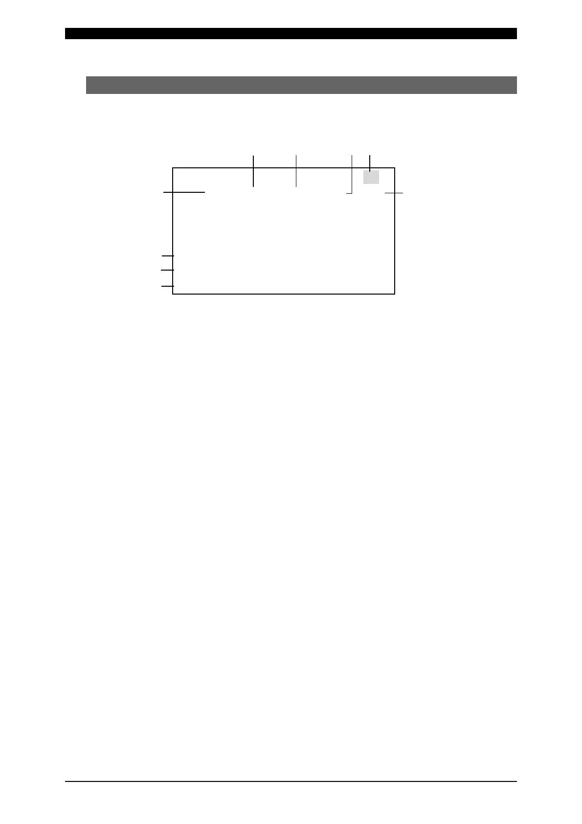
(4) MONITOR Screen
In this screen, you can confirm the operational conditions during welding.
Monitored data is displayed for each SCHEDULE.
(c) (d) (e) (a)
(b)
(g)
(h)
(i)
-MONITOR
SCHEDULE #001
TIME CURRENT VOLT POWER PULSE
WELD1 000 ms 0.00kA 0.00V 0.00kW 00.0%
WELD2 000 ms 0.00kA 0.00V 0.00kW 00.0%
WELD3 000 ms 0.00kA 0.00V 0.00kW 00.0%
STEP #(VALVE) 1(V1) 3(V2)
STEPPER COUNT 0000 0000
WELD COUNT 0000
(f)
(a) SCHEDULE #
Set the No. of the SCHEDULE to monitor. The measured values (welding
current, voltage, etc.) for welding within that SCHEDULE are displayed.
The Power Supply stores the latest measured values of each SCHEDULE No.
The stored measurement values are not erased even when the power is turned
off, and thus can be checked for the next job.
(b) TIME
The lengths of periods during which current was supplied in the course of
WELD1, WELD2 and WELD3 operations are displayed. As units of time, ms
and CYC may be selected. Either unit can be selected via the MODE SELECT
screen. (See (7)(i).)
(c) CURRENT
The welding current is displayed.
(d) VOLT
The measured voltage is displayed when the voltage detection cord is
connected and the secondary voltage is input.
(e) POWER
The measured electric power (measured current x measured voltage) is
displayed when the toroidal coil and voltage detection cord are connected and
the secondary current and secondary voltage are input.
(f) PULSE
The widest pulse among the supplied primary pulse current is displayed as a
percentage of pulse width in full wave mode. The pulse width in full wave mode
varies with the frequency setting (WELD TRANS FREQUENCY).