PN T900-013, Rev A
Making Gas Connections
To prepare for the gas connections:
• Remove any 1/16-inch or 1/8-inch VICI plugs and 1/4-inch VCR caps from
the ta7000R Rear Panel.
• Remove all other shipping caps immediately prior to connection of gas
supplies.
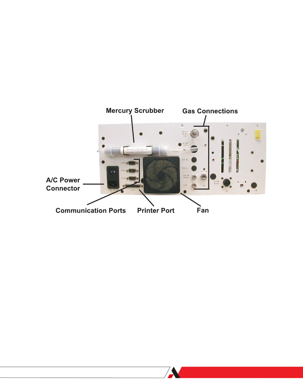
• Refer to Figure 2-3 for gas connection port locations.
Connecting the Sample and Carrier Gas
The ta7000R Monitor uses puried Sample gas as a chromatographic carrier.
Matching the Carrier gas to the Sample gas will prevent upsets caused by the
elution of the extraneous balance peak. The instrument connection is made
at the Carrier/Sample Inlet 1/4-inch male VCR port on the ta7000R Rear Panel.
Pressurize the external line to 80 PSIG (minimum 70 PSIG, maximum 90 PSIG).
Connecting Actuator Gas
The ta7000R needs high purity inert gas or CDA as valve actuator gas. Refer to
the Actuator Gas requirements in the Chapter 5 – Specications.
The instrument connection is made at the Actuator Gas 1/8-inch VICI port on
the ta7000R Rear Panel. Pressurize this external line to 80 PSIG (minimum 70
PSIG, maximum 150 PSIG).
Figure 2-3.
ta7000R Rear Panel layout,
gas and power connections.
Installation and Start-Up | 2-11
 Loading...


