PN T900-013, Rev A
Making the Electrical Connections
Connecting AC Power
Before making the AC power connections, verify that the operat-
ing voltage of the instrument matches the available AC power. The
ta7000R does not auto-select for varying power line voltages.
The instrument operating voltage is labeled on the ta7000R Rear
Panel directly above the AC Power Connector/Power Switch.
To make the AC power and communication connections:
1. Conrm the instrument power switch is in the O (“O”) position.
2. Connect the DIN AC Power Cord to the DIN AC Power Connector on the
ta7000R Rear Panel.
3. Connect the AC Power Cord to an appropriate AC voltage source.
Connecting Peripheral Equipment
All connections to the peripheral equipment are made on the ta7000R Rear
Panel.
Connecting Communications Cables
If you will be communicating with the ta7000R via a computer, connect a com-
munication cable between the computer and one of the communication ports
on the ta7000R Rear Panel.
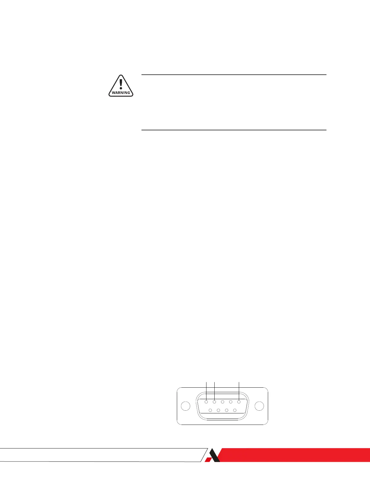
The ta7000R has three (3) communication ports (COM 1, COM 2, COM 3), all
9-pin male D-type connectors. The ta7000R uses Pin 2 is used to Transmit data
to other equipment and Pin 3 to Receive data. Pin 5 is a common ground. All
other pins are unused.
Figure 2-4.
Communication ports.
1 2 3
4 5
6 7 8 9
Receive
Ground
Installation and Start-Up | 2-13
 Loading...


