Ampcontrol Pty Ltd – ABN 28 000 915 542
IPM V2 USER MANUAL
IPM2B003 Revision 15 – MAY/18
Uncontrolled Copy - Refer to Ampcontrol Website for Latest Version
APPROVED FOR EXTERNAL DISTRIBUTION – PROPERTY OF AMPCONTROL PTY LTD – NOT TO BE REPRODUCED IN PART
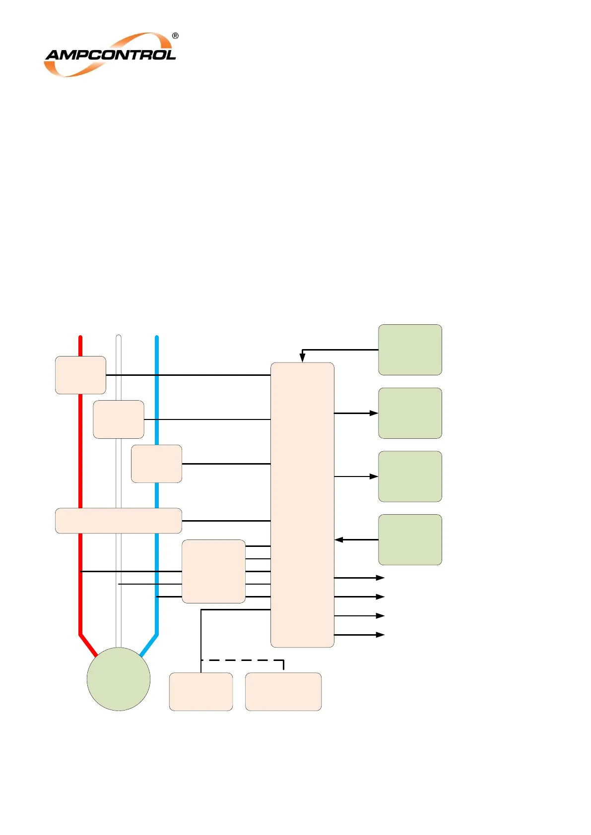
A RS485 Modbus communication port is available that can be connected to a PLC or a central
monitoring system for continuous monitoring and fault-finding.
The IPM Relay provides an isolated 4-20mA analogue output that can be configured to continuously
represent Average Current, Overload, Earth Leakage and the Insulation level of the relay.
The IPM Integration Protection Relay has 6 digital inputs (Lock, Reset, Aux, Ex-Stop, Ex-Start and MCI),
which feed into a microprocessor unit to be interpreted. The microprocessor has been programmed to
control three output relays, MCR (Main Contactor Relay), CBR (Circuit Breaker Relay) and ALM (Alarm
Relay).
All of the tripping logic and outlet control is performed by the microprocessor, so that virtually no external
control is required.
A four-line 20 character backlit LCD display combined with a keypad provides an easy to operate user
interface. The display provides easy access to all available information. A simple procedure allows
adjustment of the relay‟s settings.
Figure 3.2: IPM Block Diagram
M
RS485
Comms
Device
RTM
(Optional)
4-20mA
Analogue
Receiver
Phase CT
Phase CT
EL Toroid
External
Communications
Device (e.g. PLC)
Pilot
Diode
(Alternative)
To Outlet Contactor
Pilot Termination
CBR Output Relay
MCR Output Relay 1
Phase CT
ITM
IPM
Relay
Alarm Output Relay
MCR Output Relay 2
External
Digital
Inputs
24V AC/DC
Power
Supply