Ampcontrol Pty Ltd – ABN 28 000 915 542
IPM V2 USER MANUAL
IPM2B003 Revision 15 – MAY/18
Uncontrolled Copy - Refer to Ampcontrol Website for Latest Version
APPROVED FOR EXTERNAL DISTRIBUTION – PROPERTY OF AMPCONTROL PTY LTD – NOT TO BE REPRODUCED IN PART
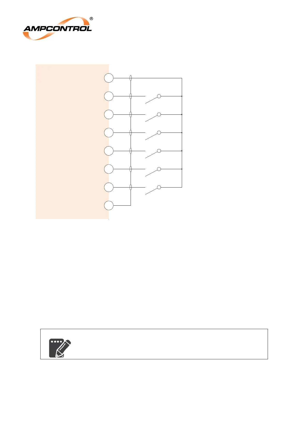
4.4.1 Digital Inputs (Terminals 1, 2, 3, 4, 5, 6, 7 & 8)
Figure 4.7: IPM Relay Electrical Connections: Digital Inputs
The IPM has a number of digital inputs to allow external devices to interact with the relay. Each of
these inputs is activated when it is shorted to the DI+ terminal (1) by a normally open contact or
pushbutton.
The MCI input is a special input that is used to monitor the state of the outlet‟s main contactor for the
IPM‟s frozen contactor protection. Wire a normally open auxiliary contact from the main contactor to
this input to allow this function to operate correctly.
For a detailed explanation of the functions of each of these inputs, refer to Section 12.6.1.
The Digital Input (DI) Screen terminal is used to terminate the screens of the cables that are used for
the digital inputs.
If the IPM is to be installed in areas of high electrical interference, it is
recommended that the wiring for the digital inputs be run in screened
cables.
IPM
Relay
Reset
3
Aux
4
5
Ex-Stop
Lock
2
+Di
1
6
Ex-Start
7
MCI
8
DI Screen*
Note*: Required in areas of high
electrical interference
Digital input reference power supply
Locked pushbutton or contact input
Reset pushbutton or contact input
(optional)
Auxiliary pushbutton or contact input
(optional)
External stop pushbutton or contact input
(optional)
Main Contactor auxiliary contact input
(for Frozen Contactor Protection)
External start pushbutton or contact input
(optional)