Ampcontrol Pty Ltd – ABN 28 000 915 542
IPM V2 USER MANUAL
IPM2B003 Revision 15 – MAY/18
Uncontrolled Copy - Refer to Ampcontrol Website for Latest Version
APPROVED FOR EXTERNAL DISTRIBUTION – PROPERTY OF AMPCONTROL PTY LTD – NOT TO BE REPRODUCED IN PART
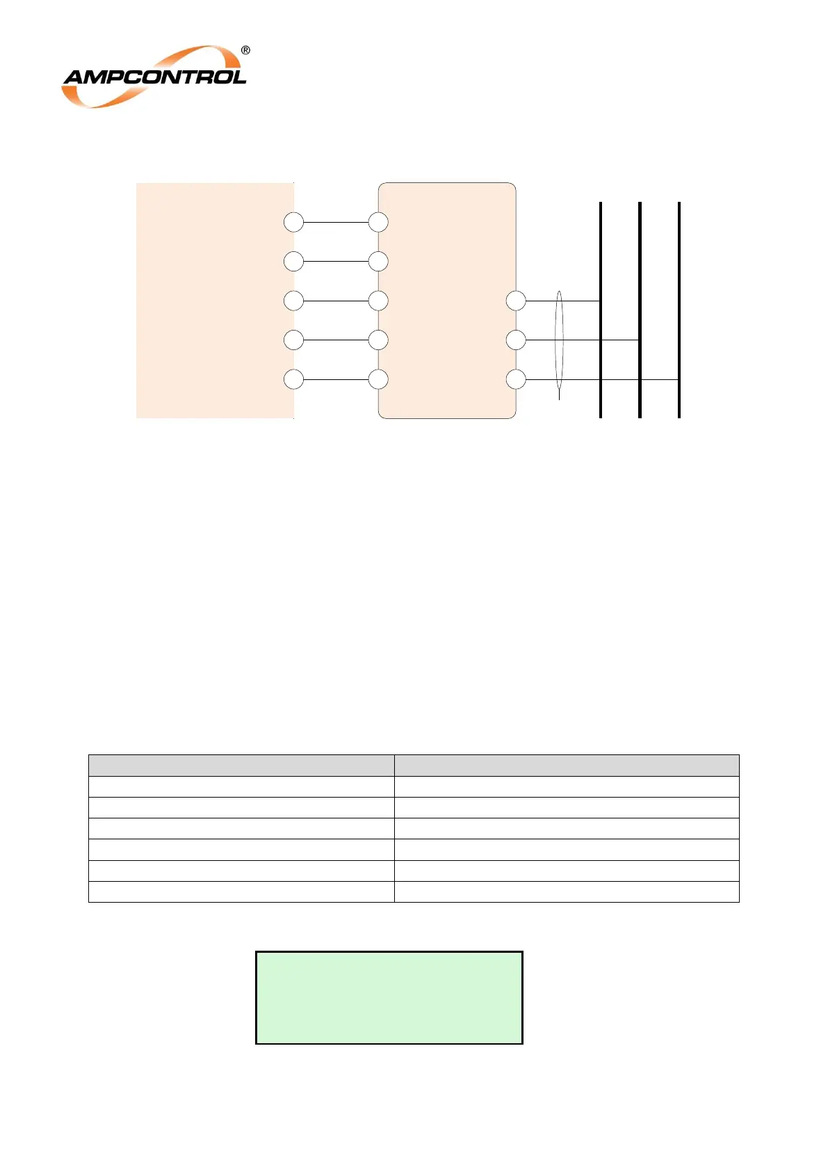
Figure 6.3: ITM Insulation Test Connections
6.2.1 Automatic Insulation Test
If an ITM Module has been selected, in the adjustable Group 1 Settings and a trip level has been set in
the adjustable Group 2 settings, then an automatic High Voltage DC „Insulation Test‟ is initiated by
operation of the start button once all starting conditions are met.
The HV DC „Insulation Test‟ commences when the IPM Relay applies voltage to the „Vtest‟ terminal of
the relay for a period of 2 seconds. This applies 30VDC to the ITM Module. A HV DC voltage is
generated in the ITM Module, which applies a voltage of 500V for 415V operation and 820V for 1000V
systems, between each phase and earth.
The IPM Relay measures the resistance to earth for all phases in parallel. At the end of the test the
result is stored in the Event Log as „It:X.XMΩ‟ If the resistance value is above the pre-set threshold the
MCR Relay picks up allowing the outlet to be energised. Additionally, if the result is equal to or below
an Alarm Level (typically 1.5 times the selected trip level) the status message „Insulat.Test Alarm‟ is
displayed on the Status Page (Level 1, Screen 1).
Table 1: Pre-set Resistance and Alarm Thresholds
Ins. Tst. Level: Selection MΩ
If the value is less than the pre-set trip level a trip occurs and is latched and saved in a non-volatile
memory. To reset the relay following an insulation test fail trip, operate the reset button.
Insulation Test 3
---- Not Active ----
Last Test : 8.6MΩ
L3: Indicates the status of the insulation test.
L4: Displays the insulation resistance as a result of the test and is retained in memory until the
next test is carried out.
IPM
Relay
Va
20
Vb
21
22
Vc
A B C
Phase Conductors
From Contactor
ITM
Vcma
Vcmb
Vcmc
Va
Vb
Vc
Flying Leads
0V
19
Vtest
18
Earth
VTEST