Ampcontrol Pty Ltd – ABN 28 000 915 542
IPM V2 USER MANUAL
IPM2B003 Revision 15 – MAY/18
Uncontrolled Copy - Refer to Ampcontrol Website for Latest Version
APPROVED FOR EXTERNAL DISTRIBUTION – PROPERTY OF AMPCONTROL PTY LTD – NOT TO BE REPRODUCED IN PART
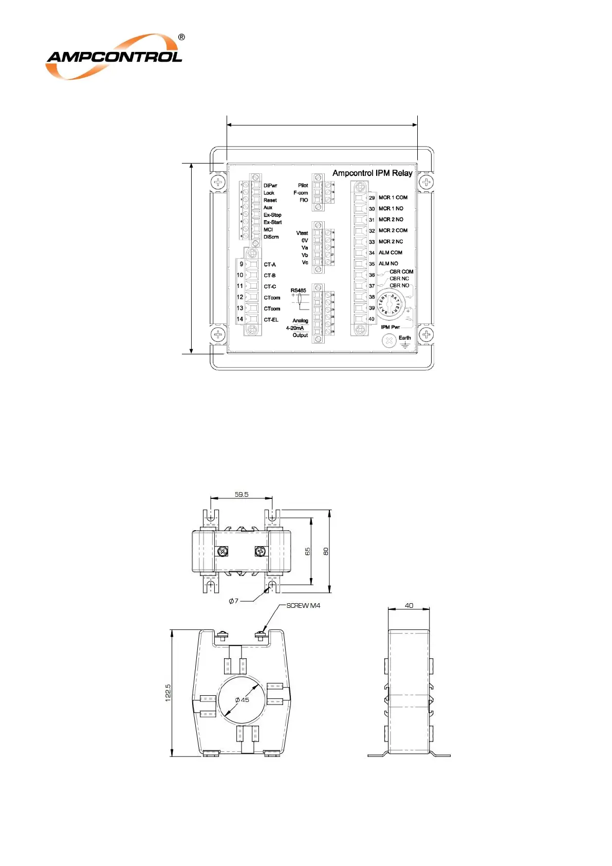
Figure 4.2: IPM Relay Rear Panel Details
4.3.2 Phase Current Transformers (CTs) & EL Toroid
The IPM uses 1000:1 or 500:5 current transformers to monitor the phase current of the outlet.
The IPM uses a 1000:1 current transformer installed around all three phases to monitor the earth
leakage current of the outlet.
These current transformers are panel mounted.
Figure 4.3: Current Transformer 45mm I.D. (Part: 101272) Dimensional Details