Ampcontrol Pty Ltd – ABN 28 000 915 542
IPM V2 USER MANUAL
IPM2B003 Revision 15 – MAY/18
Uncontrolled Copy - Refer to Ampcontrol Website for Latest Version
APPROVED FOR EXTERNAL DISTRIBUTION – PROPERTY OF AMPCONTROL PTY LTD – NOT TO BE REPRODUCED IN PART
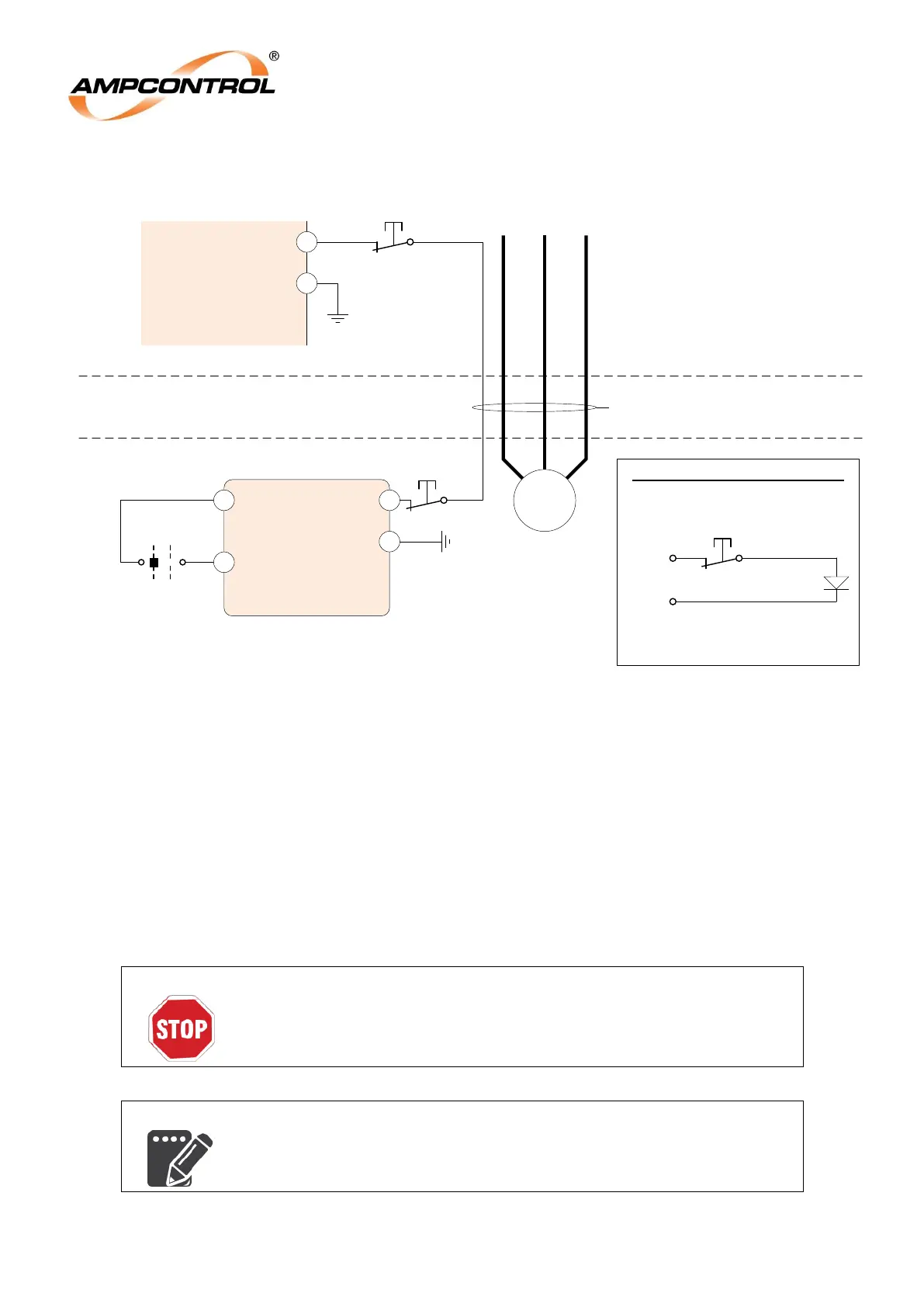
4.4.4 Earth Continuity (Terminal 15)
Figure 4.10: IPM Relay Electrical Connections: Earth Leakage Toroid
The Pilot terminal (15) is to be wired to the pilot core of the outlet‟s cable. The IPM monitors the
presence of either a termination diode, or an RTM, that is installed in the motor enclosure to ensure
that there is a continuous earth connection between the supply enclosure and the motor enclosure via
the outlet cable. The magnitude of the pilot/earth return loop impedance is also monitored via this
terminal.
In order for the earth continuity protection to function correctly, ensure that the earth connection is
correctly installed to the IPM.
If an RTM is connected, and the IPM set to remote start mode, then a remote start can be requested by
closing the input on the RTM. The input must remain closed whilst the motor is running. A stop will be
initiated if this input becomes open circuit.
The Remote Input on the RTM is not to be used for an emergency stop
function. Emergency stop pushbuttons should be wired into the
pilot circuit. A normally closed contact with a contact monitoring block
should be considered.
Remote Start is not available if the IPM is used in Diode Mode.
IPM
Relay
PILOT
15
EARTH
A B C
Phase Conductors
EC Test P/B
RTM
PILOT
EARTH
INPUT*
M
Trailing Cable
Supply Enclosure
Motor Enclosure
Emergency Stop
Start
Note*: Input is ignored if IPM
Remote Start is set to ‘NO’
Emergency
Stop
Pilot
Earth
Not available in Diode Mode
Local Control:
Remote Control:
IPM Diode Mode Pilot Connections
Stop
Remote Start
Selector