Ampcontrol Pty Ltd – ABN 28 000 915 542
IPM V2 USER MANUAL
IPM2B003 Revision 15 – MAY/18
Uncontrolled Copy - Refer to Ampcontrol Website for Latest Version
APPROVED FOR EXTERNAL DISTRIBUTION – PROPERTY OF AMPCONTROL PTY LTD – NOT TO BE REPRODUCED IN PART
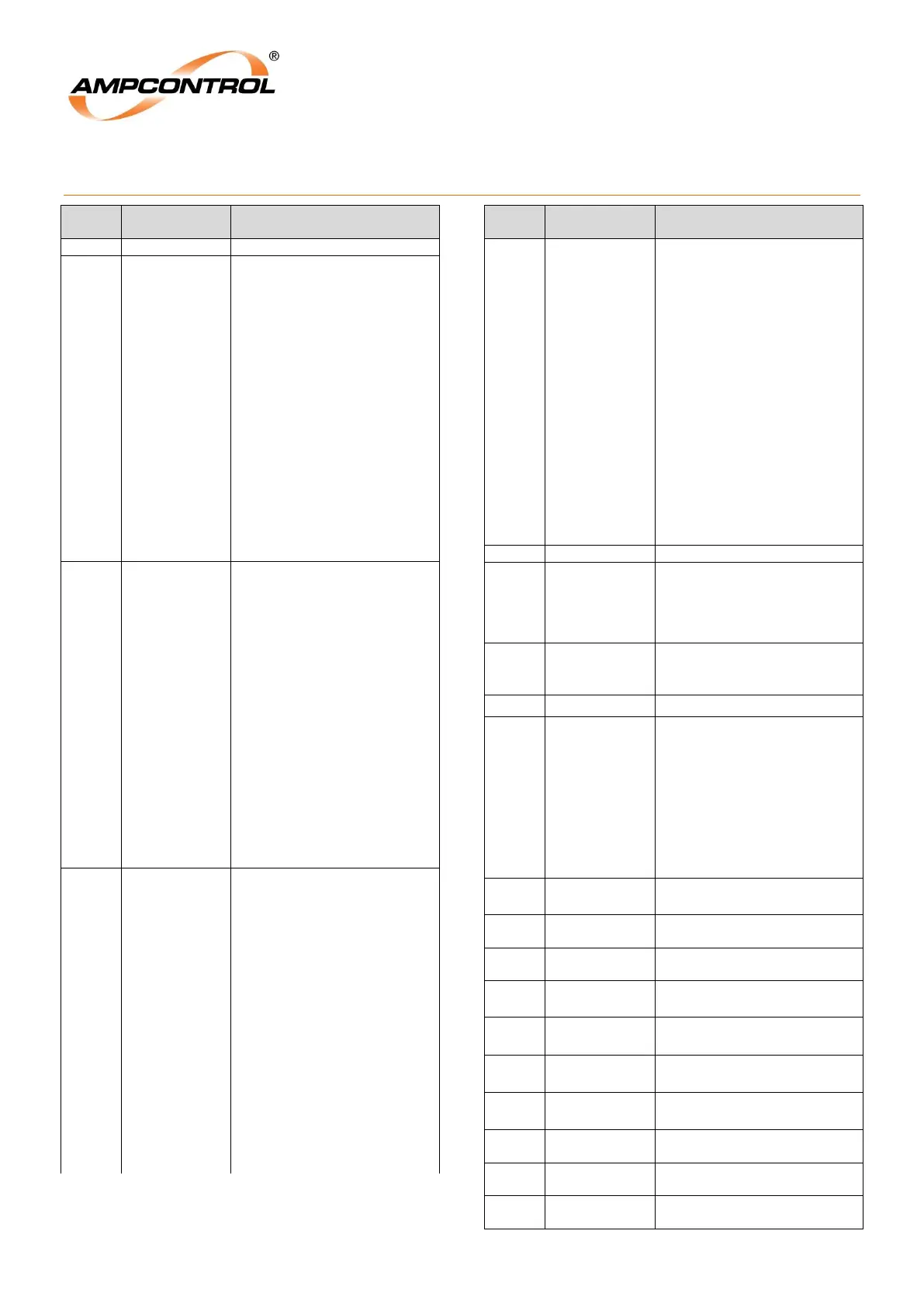
APPENDIX 5: IPM Modbus Address Table
4
Note: Bit
set when
tripped
Trip Status 1
0 = Earth Leakage
1 = Earth Continuity Trip
2 = Insulat. test trip
3 = Overload Trip
4 = Short Circuit Trip
5 = Current Balance Trip
6 = Residual Current Trip
7 = Main Contactor Fail
Trip Status 2
0 = External Stop
1 = RTM Offline Trip
2 = IPM Memory Error
3 = RTM Memory Error
4 = Stopped - IPM
5 = Modbus Timeout
6 = Modbus Stop
7 = RTM CT Ratio Error
5
Note: Bit
set when
tripped
Soft Trip Status
0 = Tripped No Volts
1 = MC Close Fail
2 = External MC Open
3 = Burp MCI Fail
4 = Under Current
5 = OTS Test Mode Exited
6 = Spare
7 = Last T:
Alarms
0 = High Current Alarm
1 = Thermal Acc Alarm
2 = Current Balance
3 = Under Cur. Alarm
4 = Earth Leakage Alarm
5 = Under Voltage Alarm
6 = Insulation Test Alarm
7 = Spare
6
Note: Bit
set when
active
ipm_stat2_byte
ipm_stat_byte
Relay Status
0 = Outlet Paused
1 = Need IPM Start
2 = Testing Insulation
3 = Closing Main Cont.
4 = Burp: MC Closed
5 = Burp: MC Open
6 = Running
7 = Manual Insulation Test
Relay Status 2
0 = Snore
1 = Snore – Close Aux
2 = RTM Version Error
3 = RTM Stop
4 = Wait on RTM Start
5 = Config Error
6 = OTS Test Mode
7 = Spare
7
Note:
Key Bits
0-7 clear
when key
pressed
keys_control
digital_inputs
Digital Inputs
0 = Spare
1 = Spare
2 = Lock
3 = Reset
4 = Aux
5 = External Stop
6 = External Start
7 = MCI
Keys
0 = Stop
1 = Start
2 = Reset
3 = Test
4 = Spare
5 = Spare
6 = Spare
7 = Spare
Pilot Forward Resistance as a
Percentage (%) of the trip
level.
Note: The IPM aims to trip at
36Ω (100%).
Pilot Forward Resistance as a
Percentage (%) of the trip
level (nominally 2k).
Insulat. Test Result (MOhms)
cur_gain_Leds
keys_menu_ra
w (in high byte)
Control Keys
0 = Up Key
1 = Down Key
2 = Left key
3 = Right key
4 = Enter key
5 = ESC Key
14 = Red LED
15 = Green LED
A Phase Current
(0…1000%)
B Phase Current
(0…1000%)
C Phase Current
(0…1000%)
Residual Current
(0…1000%)
OC Thermal Accum
(0…120%)