Ampcontrol Pty Ltd – ABN 28 000 915 542
IPM V2 USER MANUAL
IPM2B003 Revision 15 – MAY/18
Uncontrolled Copy - Refer to Ampcontrol Website for Latest Version
APPROVED FOR EXTERNAL DISTRIBUTION – PROPERTY OF AMPCONTROL PTY LTD – NOT TO BE REPRODUCED IN PART
APPENDIX 1: IPM Earth Leakage Tripping Curves
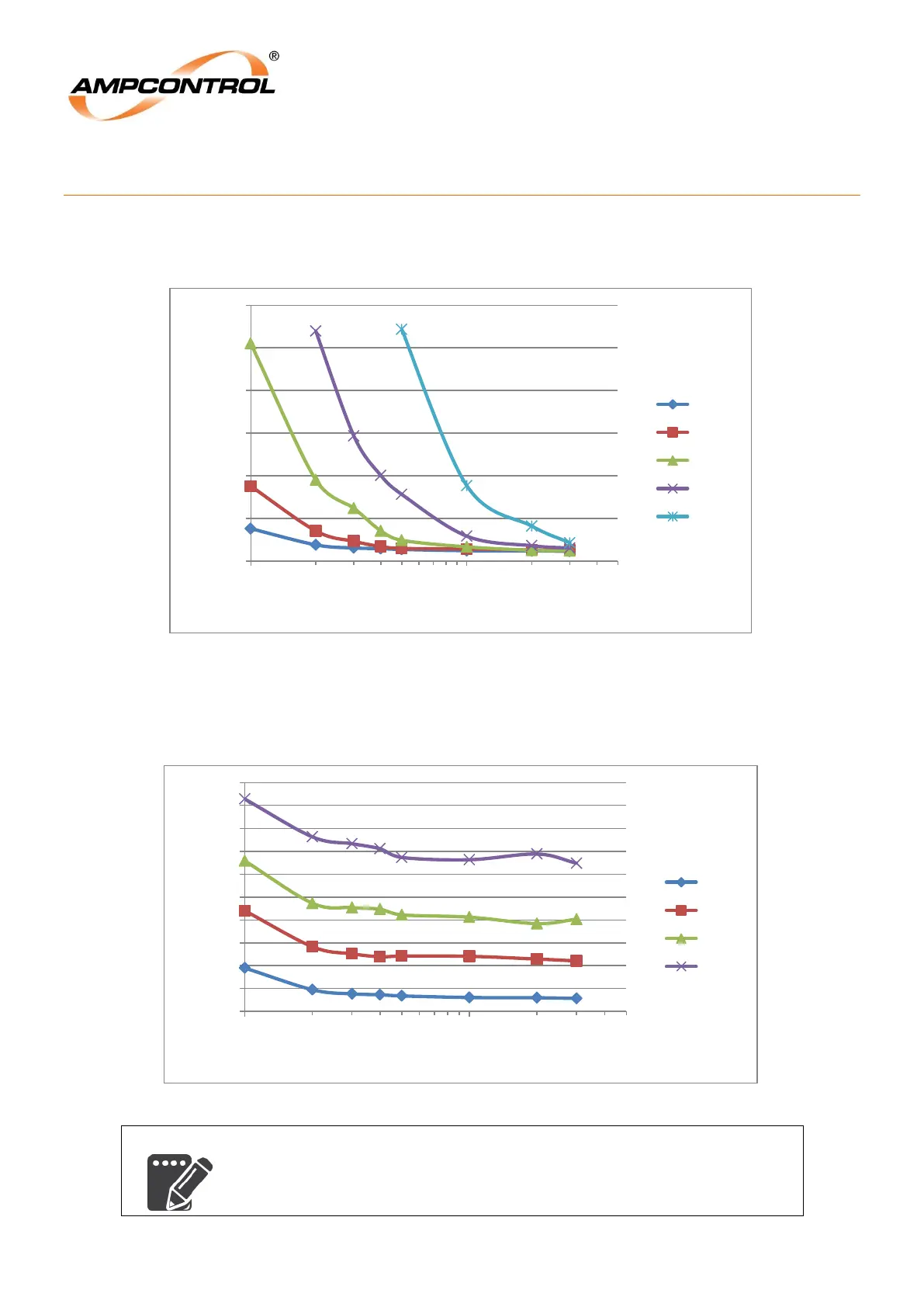
Tripping Curves for Instantaneous Trip Time Setting
The graph below shows the time taken for the IPM relay to trip for a given fault current when the relay is
set to a trip time of Instantaneous, and a selection of trip levels.
Tripping Curves for 25mA Trip Level Setting
The graph below shows the relay trip times for a 25mA trip level setting, for different trip time settings.
Similar graphs can be obtained for 50mA, 100mA, 200mA and
500mA trip levels.
0
50
100
150
200
250
300
100 1000
Trip Time (ms)
Fault Current (mA)
25mA
50mA
100mA
200mA
500mA
0
20
40
60
80
100
120
140
160
180
200
100 1000
Trip Time (ms)
Fault Current (mA)
INST
50ms
100ms
150ms