Ampcontrol Pty Ltd – ABN 28 000 915 542
IPM V2 USER MANUAL
IPM2B003 Revision 15 – MAY/18
Uncontrolled Copy - Refer to Ampcontrol Website for Latest Version
APPROVED FOR EXTERNAL DISTRIBUTION – PROPERTY OF AMPCONTROL PTY LTD – NOT TO BE REPRODUCED IN PART
4.4 Electrical Installation Information
The IPM relay provides several protection functions and, due to this, has a number of different types of
electrical connections. This section will provide details on the wiring and terminations for each of these
different types of connections.
The following sub-sections are arranged as per the terminal numbering on the rear of the unit (refer to
Figure 4.2 for terminal arrangement).
For an alternate representation of the wiring for the IPM, refer to drawing IPM2E002 in APPENDIX 6:
Drawings.
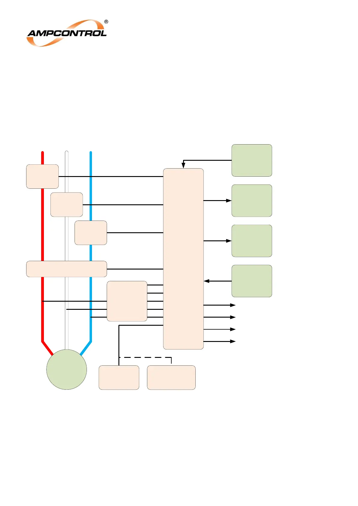
Figure 4.6: IPM Connection Block Diagram
M
RS485
Comms
Device
RTM
(Optional)
4-20mA
Analogue
Receiver
Phase CT
Phase CT
EL Toroid
External
Communications
Device (e.g. PLC)
Pilot
Diode
(Alternative)
To Outlet Contactor
Pilot Termination
CBR Output Relay
MCR Output Relay 1
Phase CT
ITM
IPM
Relay
Alarm Output Relay
MCR Output Relay 2
External
Digital
Inputs
24V AC/DC
Power
Supply