Ampcontrol Pty Ltd – ABN 28 000 915 542
IPM V2 USER MANUAL
IPM2B003 Revision 15 – MAY/18
Uncontrolled Copy - Refer to Ampcontrol Website for Latest Version
APPROVED FOR EXTERNAL DISTRIBUTION – PROPERTY OF AMPCONTROL PTY LTD – NOT TO BE REPRODUCED IN PART
12 PRODUCT OPERATION
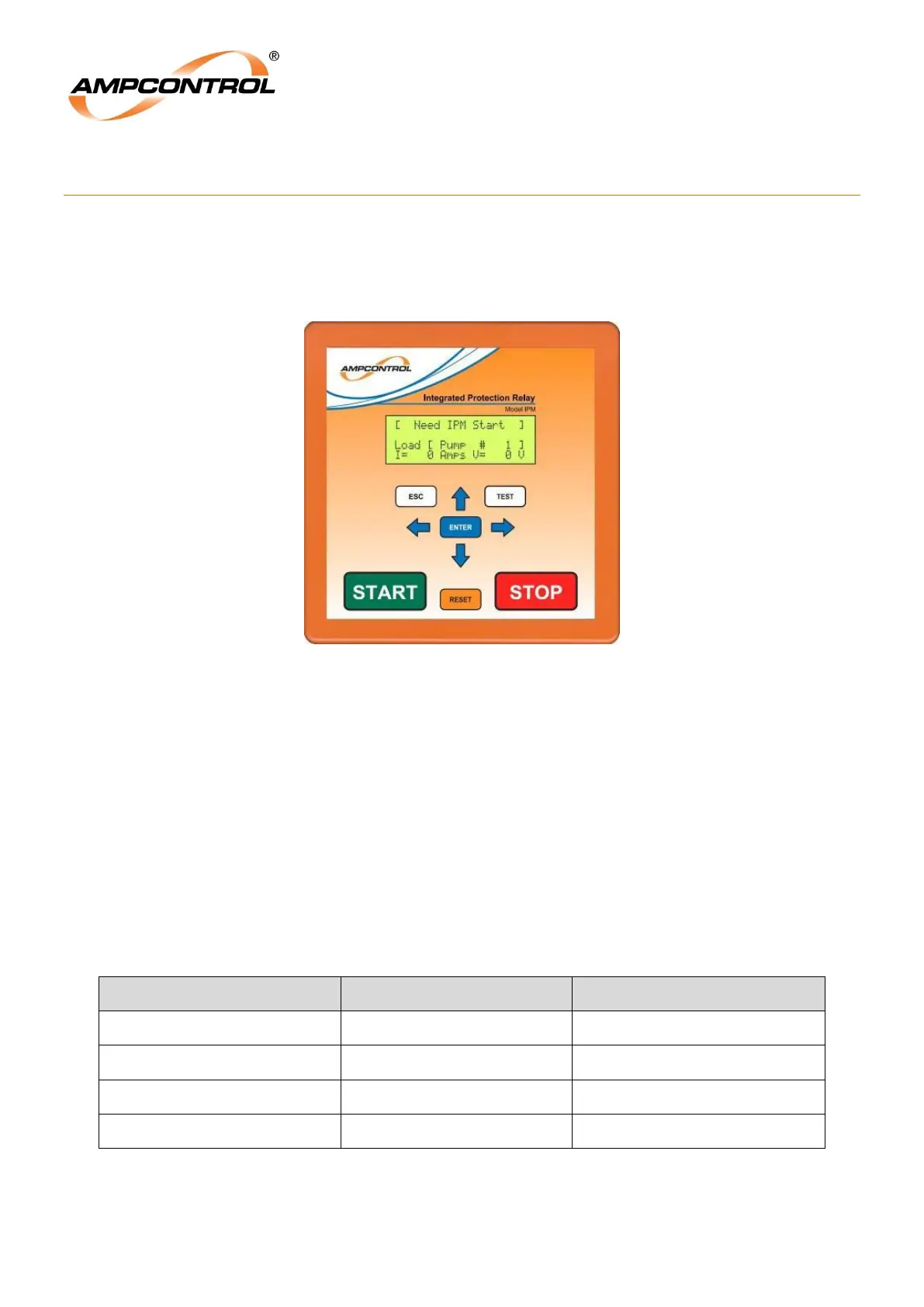
12.1 Basic Display Operation
The fascia of the IPM Integrated Protection Relay has a four line 20 character backlit Liquid Crystal
Display (LCD), Status LED and a tactile keypad. Figure 1 gives an overview of the fascia of the relay.
Figure 12.1: IPM Relay Fascia and Display
The layout of the display structure is shown on the „IPM Display Map‟, APPENDIX 4: IPM Menu
Structure. The display level is changed with the Up/Down arrow keys and the Left/Right arrow keys
control the various display screens.
The ENT and ESC keys are used to modify settings and provide hyper jump access to the display
structure.
The Reset key allows a reset following a trip condition.
The Test key is used to activate a manual insulation test.
Start and Stop keys are provided for controlling the IPM which in turn controls the MC and MCB
The Status LED is a single bi-coloured LED that can be viewed some distance from the relay. Status
indication is as follows:
Table 2: Status Indication