Ampcontrol Pty Ltd – ABN 28 000 915 542
IPM V2 USER MANUAL
IPM2B003 Revision 15 – MAY/18
Uncontrolled Copy - Refer to Ampcontrol Website for Latest Version
APPROVED FOR EXTERNAL DISTRIBUTION – PROPERTY OF AMPCONTROL PTY LTD – NOT TO BE REPRODUCED IN PART
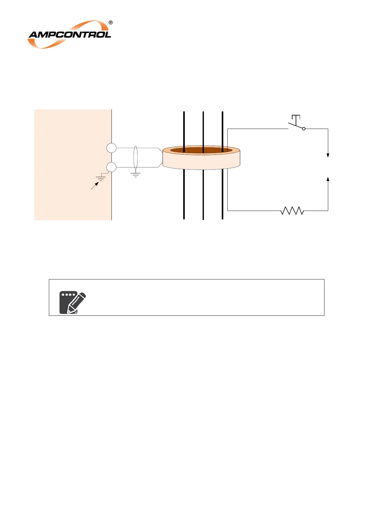
4.4.3 Earth Leakage Toroid (Terminals 13 & 14)
Figure 4.9: IPM Relay Electrical Connections: Earth Leakage Toroid
The IPM relay measures the earth leakage current using a summation toroid to provide input for the
earth leakage protection function. The toroid should be wired to the IPM using a twisted pair cable with
an overall screen.
For general information on the installation of CTs and earth leakage
toroids, refer to Section 4.4.2.
The earth leakage protection function can be tested by connecting an AC supply through the earth
leakage toroid, via a test pushbutton and a resistor. The resistor must be selected to ensure that the
earth leakage protection trips as required.
IPM
Relay
14
13
A B C
Phase Conductors
AC Control
Supply
EL Test P/B
Test Resistor
Optional EL Test Circuit
1000:1 CT
88mm I.D.
CTcom
Internally
Earthed
CT-EL