Ampcontrol Pty Ltd – ABN 28 000 915 542
IPM V2 USER MANUAL
IPM2B003 Revision 15 – MAY/18
Uncontrolled Copy - Refer to Ampcontrol Website for Latest Version
APPROVED FOR EXTERNAL DISTRIBUTION – PROPERTY OF AMPCONTROL PTY LTD – NOT TO BE REPRODUCED IN PART
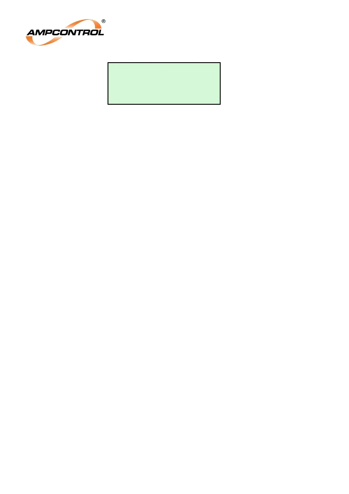
Earth Continuity 3
R:27% L: 0% V#10
Load [WPump # 1]
L3: Shows the earth continuity resistance (R) of the pilot – earth loop and the leakage (L)
between the pilot and earth conductors as a % of the trip levels. When either value reaches
100% a trip occurs. The version of the software is also indicated.
L4: Shows the Load Type and Number (from the connected RTM unit).
Pilot Trip Time is adjustable to allow for operation in noisy electrical environments. The trip times can be
selected at „Pilot Trip t‟ (Level 6, Screen 15) and can be set to 80, 120, 160, 200, 300, 400 and 500ms.
The leakage trip setting is fixed at 1850Ω.
Clause 5.3 of AS/NZS 2081 requires total clearance trip times <500mS, this includes interposing relays,
contactors and circuit breaker opening times. An EC trip time of up to 500mS is entirely appropriate
where touch potentials are managed appropriately, however in all cases the EC trip time should be as
low as is reasonably practical.
The purpose of earth continuity protection is to continuously monitor the integrity of the return earth
resistance. The earth continuity protection relay cannot explicitly monitor the return earth resistance
alone, and instead monitors the resistance of the pilot-earth loop. In all cases, the resistance of the pilot-
earth loop will be higher than the return earth resistance itself, and so is conservative. That is, the return
earth resistance can be no higher than the trip setting of the earth continuity relay.
There are two aspects to earth continuity monitoring:
(1) To actively remove power from an outlet in case of live uncoupling, and;
(2) To monitor incremental changes in the resistance of the earth return path to ensure that
leakage currents under both normal and fault conditions do not result in dangerous touch
voltages.
The IPM relay meets the requirements of AS/NZS2081 which sets a limit on the maximum clearance
time that can be utilised for earth continuity protection of 500ms. This specifically addresses the risk
associated with live uncoupling. That is, in restrained receptacles suitable for mining applications the
pilot pin disengages before the earth connection and the upper limit of 500ms removes power before a
user can practically complete disconnection and inadvertently come into contact with live exposed
connections or generate a hazardous electrical condition.
Similarly, incremental changes in the return earth resistance can occur over time through the normal
process of coupling and uncoupling electrical connections and the ingress of dust and contaminants as
mining progresses. The electrical distribution system will be designed so that the worst case touch
potential under fault conditions is developed with the upper limit of return earth resistance set by the
earth continuity trip resistance. It should be noted that a modest increase (even an increase above the
trip setting) of earth return resistance is not immediately dangerous in the majority of situations – a touch
potential is normally only generated in case of an earth fault. Unlike an earth leakage clearance time,
there is no requirement that the earth continuity trip time be instantaneous, nor is there a defined link
between EC clearance time and significantly improved safety outcomes. Under Australian Standards
earth continuity protection trip times <=500ms are generally acceptable and will normally meet the
requirements of (1) & (2) for most applications.
The trip time for earth continuity should be chosen in the same way as an earth leakage trip current
setting. In all cases, the earth leakage trip current should be as close as possible to the normal (non-
fault) EL current that does not cause a nuisance tripping. Similarly, the earth continuity trip time should
be as low as practical to not cause a nuisance trips. In low noise applications (eg: simple DOL motors