L0118G
4-4
6. Enter the price and press * to save this price,
then do one of the three things listed below:
a. To save the selection at this price
press * again.
b. Press 1 to save all the tray
selections at this price.
c. Press 2 to save all the vendor
selections at this price.
7. The prices as set will be maintained by the
vendor even if there is a power failure or if
the machine is unplugged: however, prices
will need to be reset if the configuration of
motors or trays is changed.
8. Using the * or # keys, scroll through the
menu, or exit the service mode by pressing
the mode switch or closing the vendor door.
4.3 ON-SITE INSTALLATION
Remove the Shipping Boards
1. Split the shipping boards by inserting a
crowbar or wedge into the slots at either end.
2. If necessary, lift the vendor to remove the
broken boards using properly rated
equipment. Do not tilt the vendor. Do not
attempt to lift the vendor with a 2-wheel hand
truck.
Placing the Vendor in Location
1. Place the vendor within 5 feet of the
designated power outlet. The power outlet
should be accessible when the vendor is in
position, and the ventilation opening in the
back of the vendor must be clear of
obstructions.
2. For refrigerated models, allow at least 4
inches between the wall and the back of the
vendor for air circulation.
3. Make sure the vendor does not block
walkways or exits.
4. Do not place the vendor in a location where
it can be struck by vehicles.
5. Leave at least 18 inches between a wall and
the hinge side of the vendor to prevent the
door hitting the wall when opened, or use a
protective wall bumper. The door must open
wide enough to allow the trays to be pulled
out.
6. The vendor is designed to meet the 1991
ADA guidelines for persons in wheelchairs
using a parallel approach (side of wheelchair
adjacent to front of vendor). Make sure there
is adequate room to maneuver a wheelchair
into this position in front of the vendor.
Leveling the Vendor
For safe operation and for proper coin handling by the
coin changer, the vendor must be level.
1. On the bottom of the vendor are four (4)
threaded leveling legs located at the corners
of the cabinet and a fifth support screw
under the door. Before beginning, be sure
that all five leveling legs are screwed in
completely.
2. With the door closed and locked, check the
four main legs and adjust any leg that is not
contacting the floor. Make sure the support
screw under the door is all the way up and is
not contacting the floor at this time.
3. Place a level on top of the cabinet and check
for horizontal from side-to-side.
4. Adjust the leveling legs on the low side one
turn at a time until the cabinet is level.
5. Repeat the last two steps to level the vendor
front-to-back.
6. After the vendor is level, adjust the support
screw under the door until it contacts the
floor.
False Leg Installation
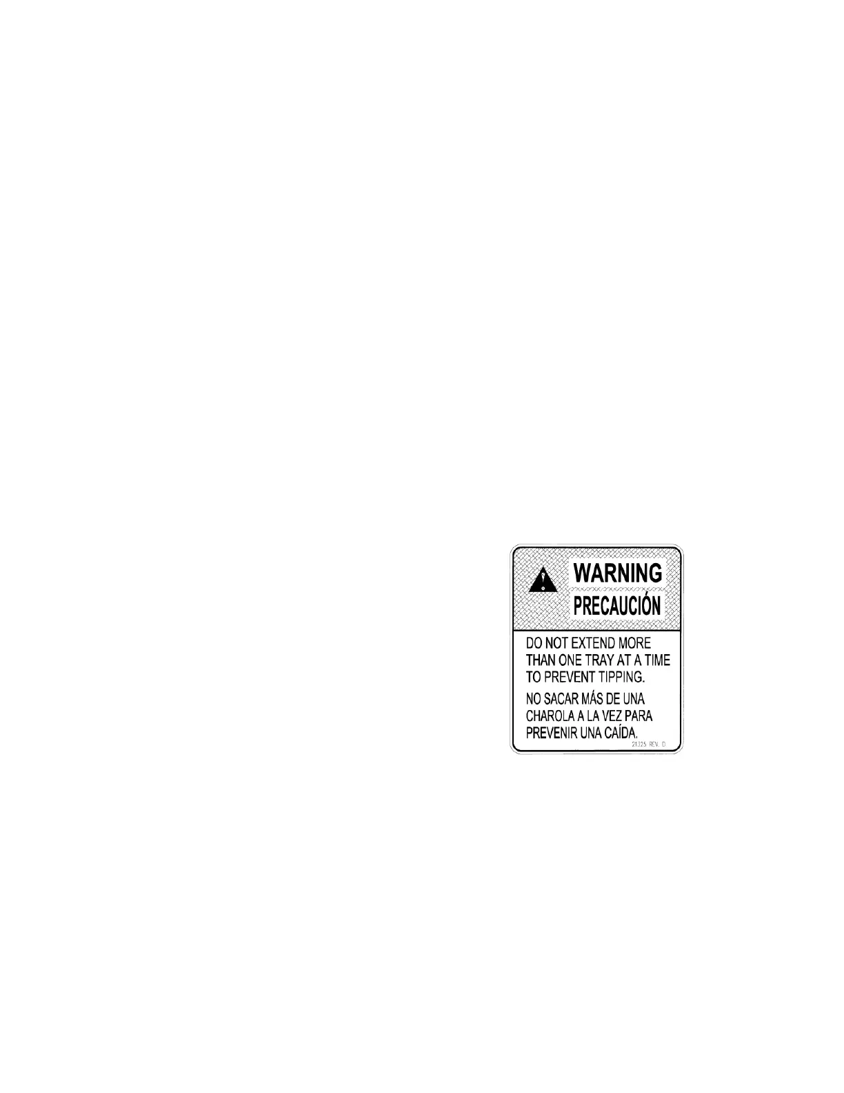
WARNING
The False Leg helps to prevent the machine from
tipping forward when the vendor door is open and
one or more bottle trays are extended. Failure to
install the false leg on vendors with bottle trays
may result in serious injury (Refer to Figure 4.2).
Figure 4.1 Tip-Over Warning
CAUTION: Wear gloves-edges may be
sharp! Always wear eye
protection when servicing
vendor!
TOOLS REQUIRED:
1/4” Nut driver or socket wrench
1. Align the holes in the top of the false leg with
the 1/8” holes on the left side of the bottom
of the door (Refer to Figure 4.2). The closed
end of the false leg should be facing forward.
2. Install screws through the holes and tighten
until snug. Do not over tighten.