L0118G
8-5
Replacing Optional LED Lamps
1. Open the door.
2. Turn off the power to the control board by using
the power switch.
3. Locate the LED harness and remove it from the
MDB harness.
4. Remove the screws holding the large and small
P-clips, and remove the LED lamps.
5. Install the replacement LED lamps, using the
small and large P-clips and the screws.
6. Connect the LED harness to the MDB harness.
7. Turn on the power to the control board.
8. With the LED lamps operating, turn the LED
lamps to direct the light into the vendor.
9. Close the vendor door.
8.10 DEFROSTING THE EVAPORATOR COIL
Excess moisture accumulating inside the cabinet may
freeze in the evaporator coil. As the coil becomes
blocked all useful chilled air is also blocked.
1. Unplug the vendor
2. Open the door.
3. If the vendor has entered an H&S vending hold,
the food products should be disposed of.
4. Place a fan on the floor in front of the vendor to
direct room temperature air into the back of the
cabinet.
5. Do not use any tools or electrical appliances to
chip at, heat up or otherwise “speed up” the
defrosting action around the coil. Do not
puncture the coil.
6. Check to see if the base under the evaporator
drain pan is the non-freezing type, which has
two large rectangular vent holes formed in its
longest side. If the base is made without these
large holes contact AMS to arrange for a Non-
Freezing Evaporator Drain Pan Kit (Refer to Kit
Drawing 21351).
7. Look for the source of excess moisture.
8. Look for broken or leaking product. Dispose of it
and clean up the liquid.
9. Inspect the vend hopper and clean it of liquids
and broken containers.
10. Check to make sure the vend hopper door
doesn’t hang open.
11. Check that the gasket of the chiller housing is
securely contacting the cabinet and is sealing it
on all sides.
12. Check to ensure the sealing putty is firmly in
place around the two openings on the rear, right
hand edge of the chiller housing. Use more
putty if it is missing or is not enough.
13. Check the door gasket around the cabinet
opening. It should be intact.
14. Check to see if the door closes squarely on all
four sides and the lock draws the door firmly
against the gasket.
15. After the evaporator coil has been defrosted,
clean up any water inside the cabinet.
16. Close the door.
17. Plug in the vendor and allow vendor to cool
down before loading perishable products.
8.11 TESTING THE TEMPERATURE SYSTEM
(Health and Safety)
Note: This feature is only available when the P/N
3427 Software is installed.
1. Enter the service mode (Refer to Section 6.0).
2. Press “#” or “
*” until the Temperature section
appears, then press 2 to view the current set
point. The temperature will be displayed in both
Fahrenheit and Celsius. The setpoint of the
vendor must be 41°F or lower for the H&S
option to be enabled.
3. Press 5 to initiate the NAMA H&S 15 minute
Automatic Shutoff Controls test. At this point the
sensor can either be temporarily disconnected,
causing the controller to assume a temperature
of 125°F/49C, or relocated outside the cabinet.
Relocating the sensor outside will allow the
sensor to be tested as well.
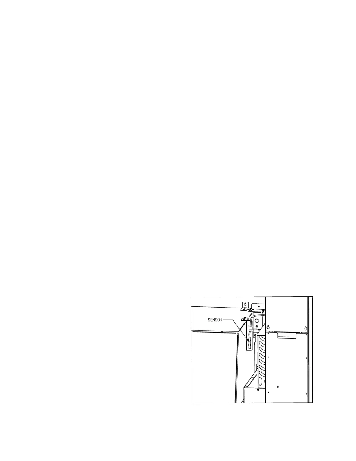
4. The sensor is mounted to its bracket using two
spring clamps (Refer to Figure 8.4). To remove
it, first unwrap the sensor wire from the two slots
in the bracket, and then slide the sensor out of
the two spring clamps.
5. Relocate the sensor outside the vendor, and
allow to warm up (above 41°). Carefully close
the door. The temperature may be monitored by
pressing the * button. The sensor bulb has a
20-25 second response delay to minimize
hysteresis error before the correct temperature
is displayed.
15 minutes after the door is closed, the display should
read “OUT OF SERVICE- HS1”. The vendor will not
vend protected products until the door is opened and
the error is cleared (Refer to Section 6.2).
Figure 8.4 Temperature Sensor