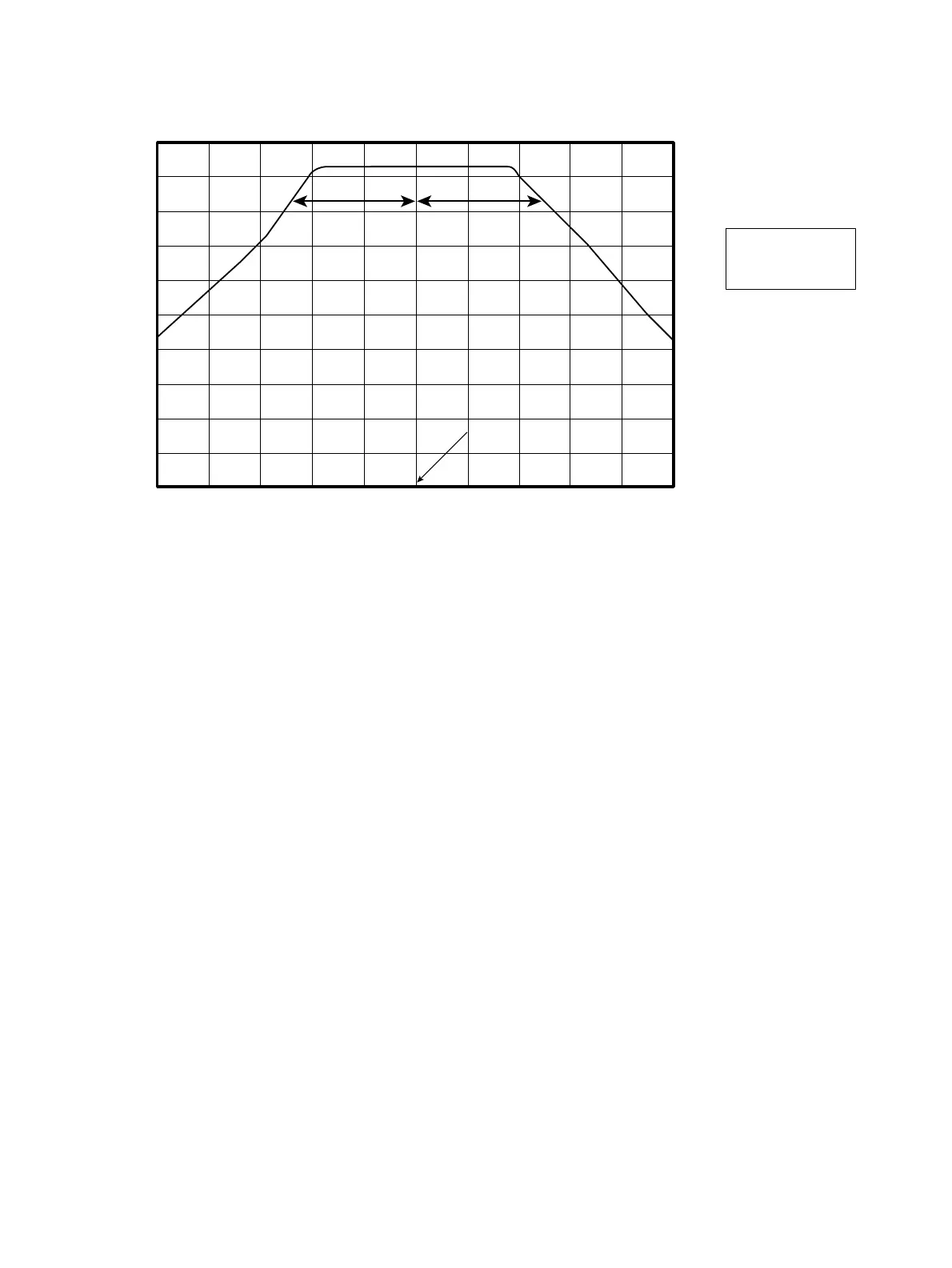
4-21
AB
10 dB down point
A=B
Center frequency
(30 GHz)
(7) YTF Sweep adjustment
1) Initialize the spectrum analyzer (Press key “preset”, followed by Key “F1”).
2) Set 6769B Signal generator output to :
Frequency : 26.2 GHz
RF level : -10 dBm
3) Set Marker of the spectrum analyzer to 26.2 GHz (Press keys “Marker” + “2”+“6”+“.”+“2”+“GHz”) and adjust
R41 on the 2nd Converter (refer to Fig. 3-2-5) to make Marker read maximum.
4) Set Pre-selector bias value to 0 by pressing keys “frequency” + “F5” (Pre-selector Tuning) + “F2” (Manual).
5) Set the marker function to delta marker mode (Press keys “Marker” + “F2”).
6) Change Pre-selector bias value to negative value by the knob on the front panel as to read the level of delta marker
to -6 dB ±1 dB.
Now read Pre-selector bias value (P1).
7) Change Pre-selector bias value to positive value by the knob on the front panel as to read the level of delta marker
to -6 dB ±1 dB.
Now read Pre-selector bias value (P2).
8) Adjust R41 (rough adjustment) or R42 (close adjustment) on the 2nd Converter (refer to Fig. 3-2-5) until P1 + P2
become below ±8, to repeat the procedure 4) to 8).
4.2 Troubleshooting







 To Next Page