6-3
6.3 Test group 1
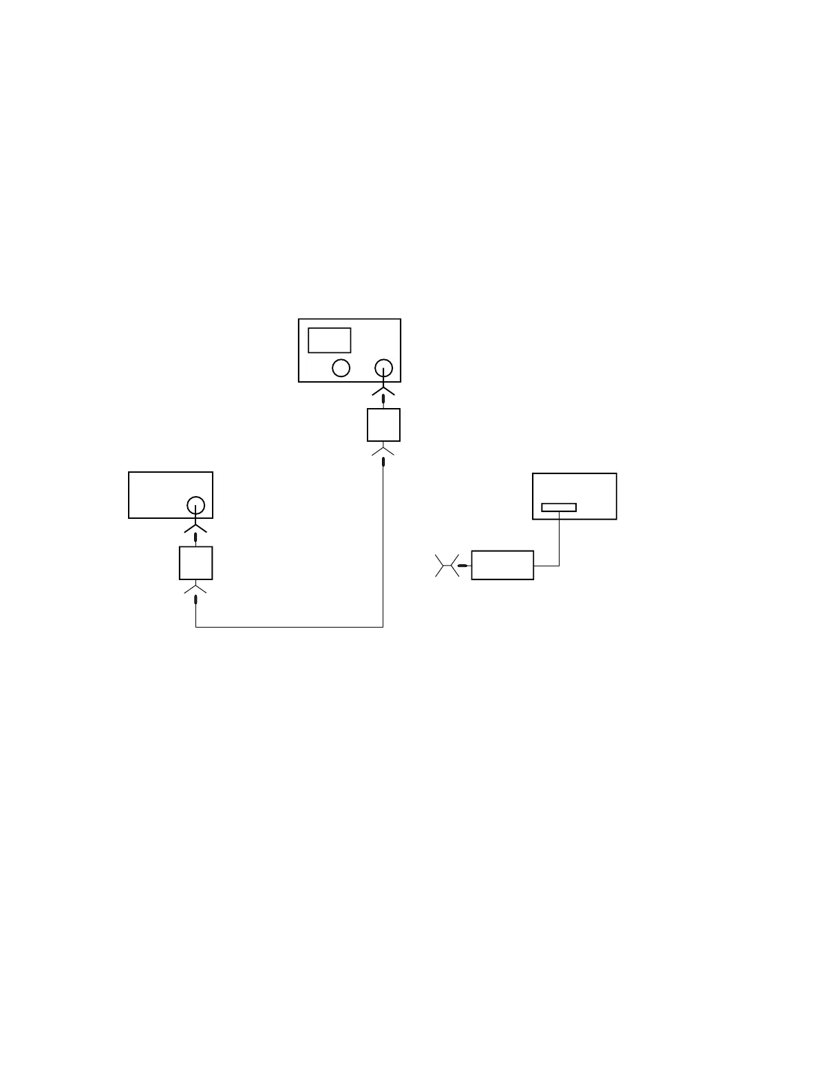
6.3.1 Test items :
Frequency response
6.3.2 Setup :
RF Input
6769B
The spectrum analyzer
RF Output
3 dB
3 dB
(1) Use power meter at 6769B
calibration
Power meter : ML4803A
ML2437A
(For MS2667C or MS2668C)
Power sensor : MA4701A
MA4705A (For MS2665C)
MA2444A (For MS2667C or MS2668C)
Fig. 6-3-1
At the measurement of frequency response, connect the spectrum analyzer’s RF Input to 6769B RF OUTPUT through a
signal feeder. The signal feeder consists of a coaxial cable (e.g. SUCOFLEX) less than 1 m length and two 3 dB attenu-
ators (41KC-3) attached to each end of the cable.
(1) At the calibration of power output, connect the end of the feeder to power sensor.
Note :
1) The coaxial cable must be with a frequency range over the spectrum analyzer’s range.
2) Use a torque wrench for tightening each connection.
3) After the power calibration, do not disconnect the connections of the 6769B and the signal feeder in order to
keep the measured data valid.
6.3 Test group 1