6-5
6.4.2 Setup :
(1) Use power meter at MN74A’s
COM output or 6769B output
calibration
Power meter : ML4803A
or ML2437A
Power sensor : MA4701A or MA2444A
RF Input
The spectrum analyzer
MG3633A
6769B
RF Output
Output
MN63A
P-ATT
MN74A
CH1
COM
CH3
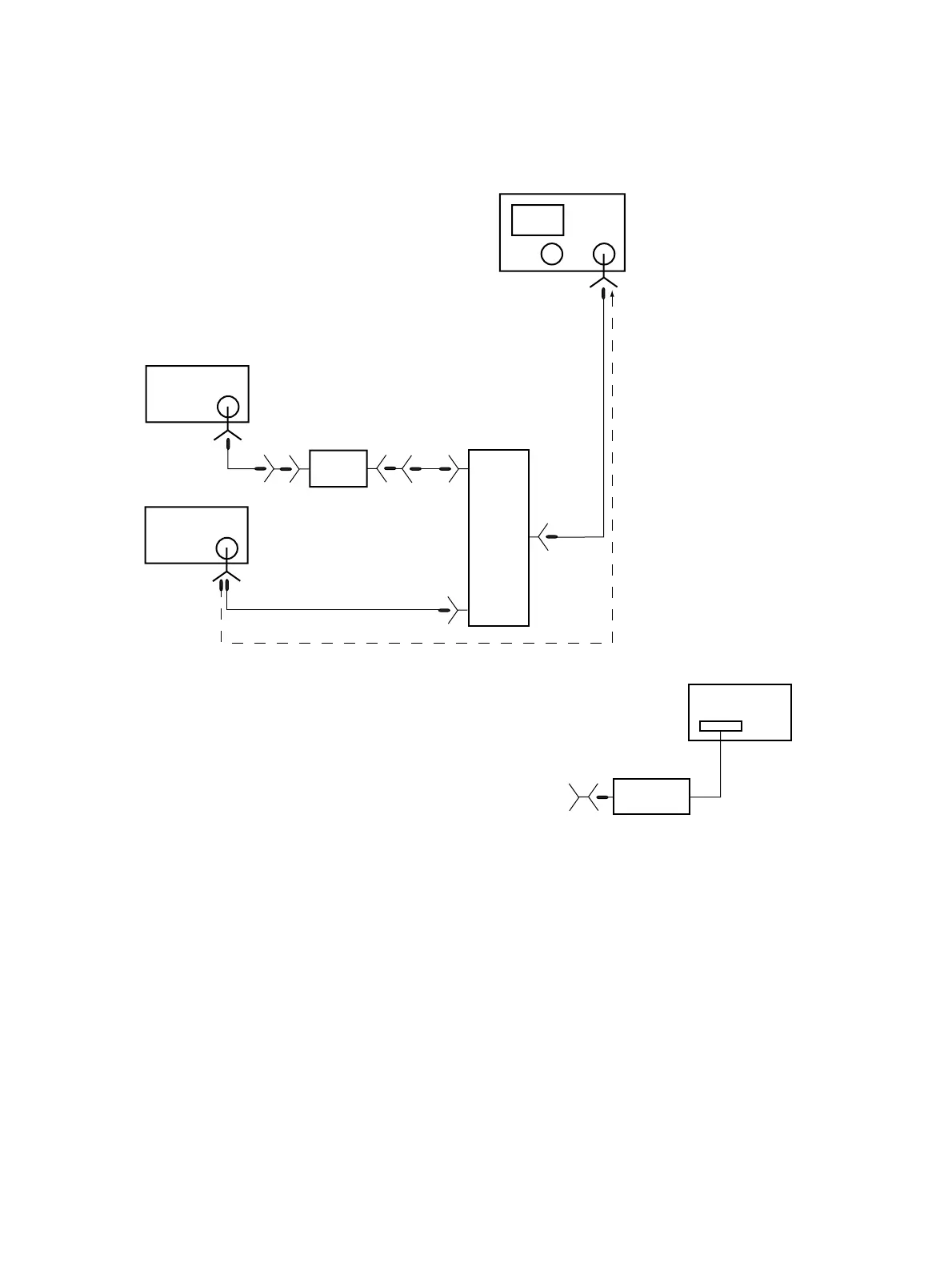
Fig. 6-4-1
On MN74A, connect CH1 to MG3633A OUTPUT through MN63A and connect CH3 to 6769B RF OUTPUT.
At the measurement, connect the spectrum analyzer’s RF Input to COMMON of MN74A through a signal feeder. When
Image response or/and Multiple response of MS2667/68C are measured, connect the spectrum analyzer’s RF Input to
6769B RF OUTPUT through a signal feeder.
(1) At the calibration of power output, connect the end of the signal feeder to the power sensor.
6.4 Test group 2