4-29
(3) Assembling YTF
3
(For F2626)
If YTF is OPEN LOOP YIG FILTER (F2626), perform this assembling procedure.
If YTF is F2626 MODULE or MLFP1312 MODULE, please perform (4) assembling procedure.
1) Tighten the S4 screws.
2) Connect 40GHz H.MIXER’s connector to YTF
3
’s connector.
At this time, make sure that the lower surface cover of 40GHz H.MIXER is set parallel to Plate
4
. (Refer to
Fig.4-3-1)
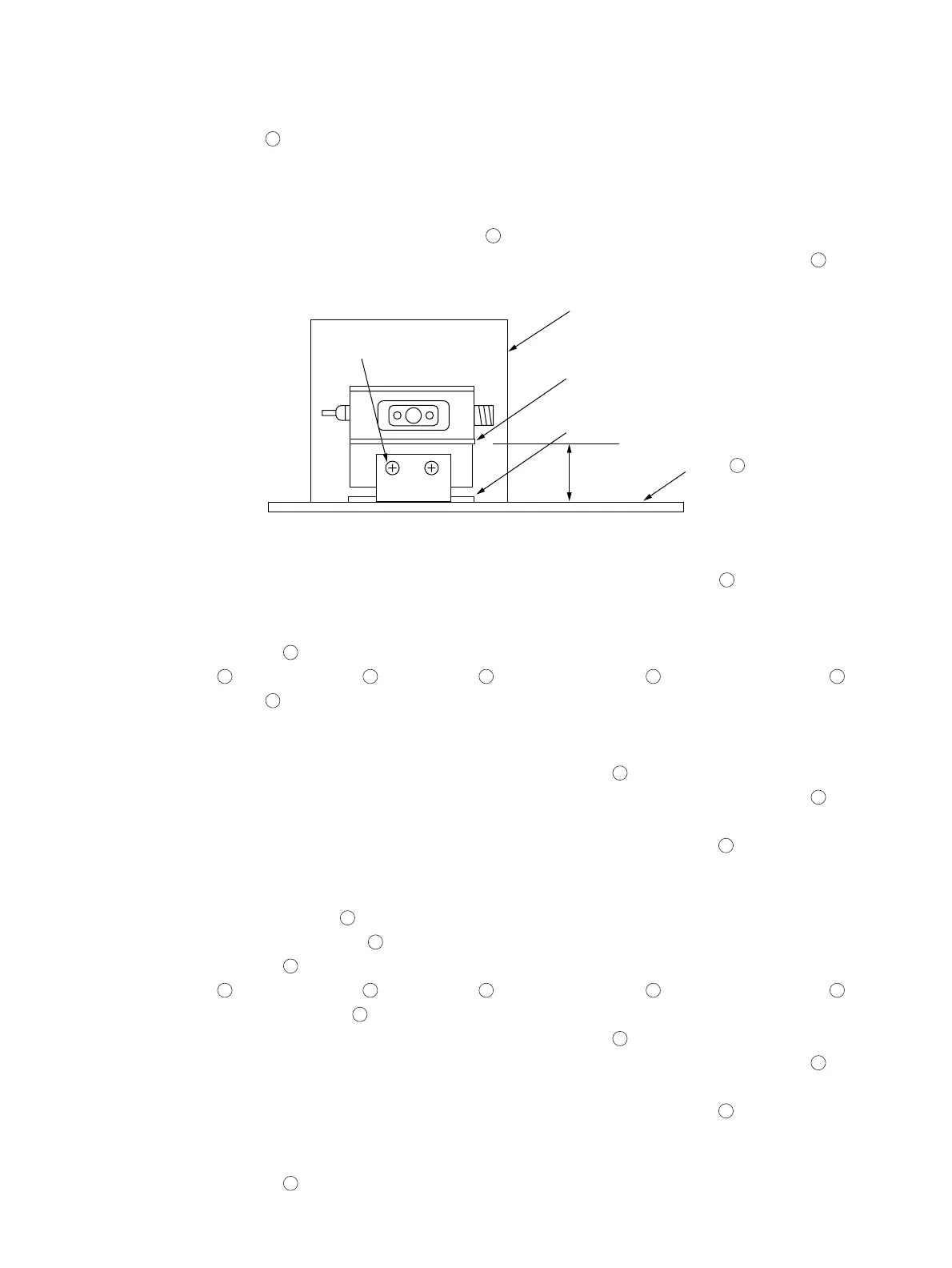
S7
YTF
Lower surface cover
of H.Mixer
Mixer Angle
parallel
Plate
4
Fig. 4-3-1
3) Tighten the S7 screws. while making sure that the Mixer angle rests on the Plate
4
thoroughly with no gap
between them ( Refer to Fig.4-3-1 ). If there are no S7 screws, perform procedure 4).
4) Tighten the S5 screws.
5) Attach the plate
4
and tighten the N1 nuts.
(YTF
3
, 40GHz H.MIXER
5
, Coupler/Amp
2
and Switched Doubler
6
are Attached on the plate
4
).
(4) Assembling YTF
3
(For F2626 MODULE or MLFP1312 MODULE)
If YTF is F2626 MODULE or MLFP1312 MODULE, perform this assembling procedure. If YTF is OPEN LOOP
YIG FILTER (F2626), please perform (3) assembling procedure.
1) Connect 40GHz H.MIXER’s connector which is connected to YTF
3
.
At this time, make sure that the lower surface cover of 40GHz H.MIXER is set parallel to Plate
4
. (Refer to
Fig.4-3-1)
2) Tighten the S7 screws. while making sure that the Mixer angle rests on the Plate
4
thoroughly with no gap
between them ( Refer to Fig.4-3-1 ). If there are no S7 screws, perform procedure 3).
3) Tighten the S5 screws.
4) Attach the Coupler/Amp
2
and tighten the S3 screws.
5) Attach the Switched Doubler
6
and tighten the S6 screws.
6) Attach the plate
4
and tighten the N1 nuts.
(YTF
3
, 40GHz H.MIXER
5
, Coupler/Amp
2
and Switched Doubler
6
are Attached on the plate
4
).
(5) Assembling 40GHz H.MIXER
5
1) Connect 40GHz H.MIXER’s connector which is connected to YTF
3
.
At this time, make sure that the lower surface cover of 40GHz H.MIXER is set parallel to Plate
4
. (Refer to
Fig.4-3-1 )
2) Tighten the S7 screws. while making sure that the Mixer angle rests on the Plate
4
thoroughly with no gap
between them ( Refer to Fig.4-3-1 ). If there are no S7 screws , perform procedure 3).
3) Tighten the S5 screws.
4) Attach the plate
4
and tighten the N1 nuts.
4.3 Mechanical configuration