3-17
3.2 Troubleshooting
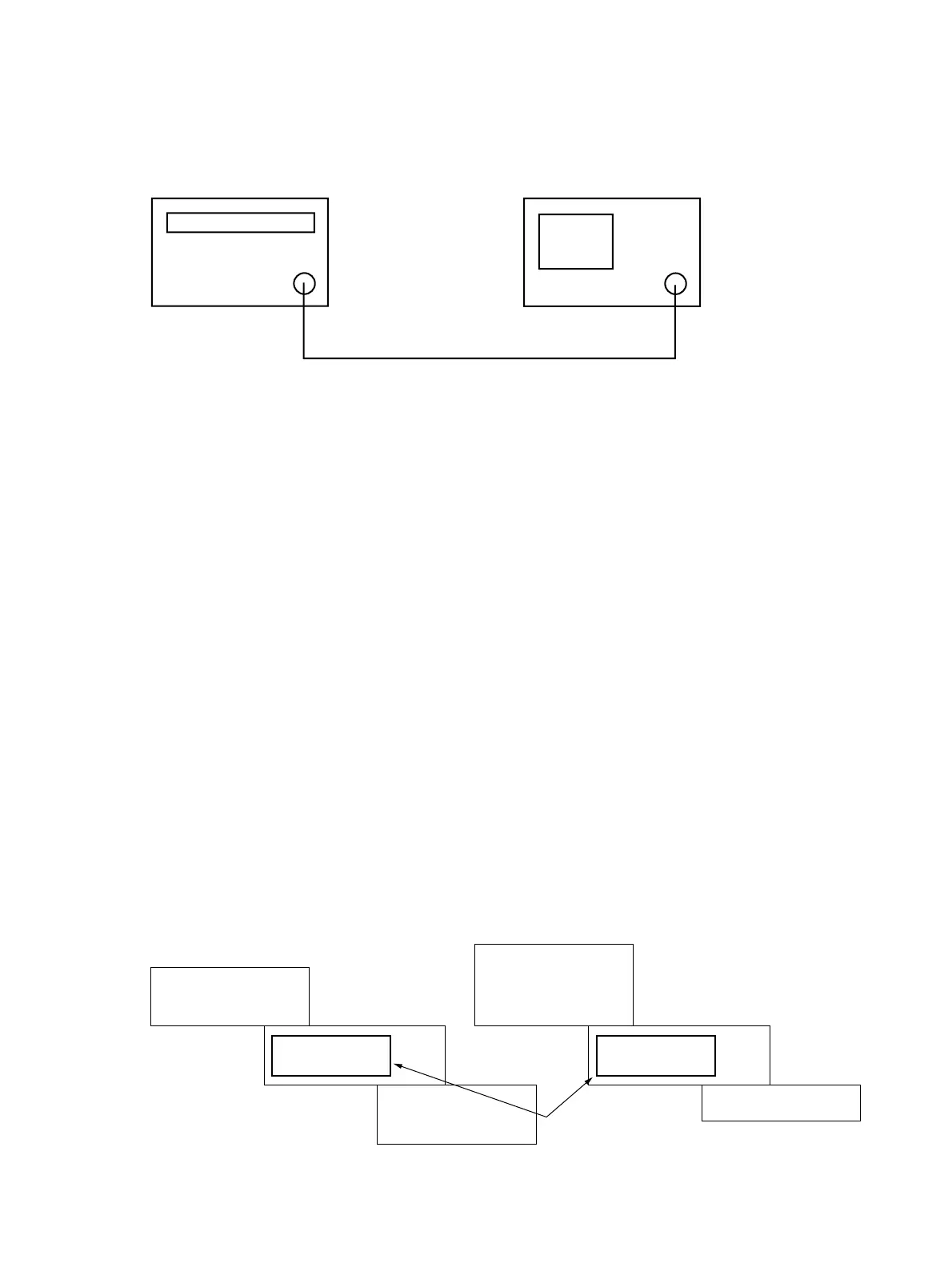
Setup for the procedure (1), (2) :
RF Input
Output
MG3633A
The spectrum analyzer
Fig. 3-2-1
Connect the spectrum analyzer RF Input to MG3633A OUTPUT.
Setup for the procedure (3) :
(1) Connect digital multimeter HI input to the X3 terminal on LOCAL-SP2 PC board. (Refer to Fig. 3-2-4)
(2) Connect digital multimeter LO input to the spectrum analyzer’s common.
Setup for the procedure (4) :
(1) Connect digital multimeter HI input to the X21 terminal on LOCAL-SP2 PC board. (Refer to Fig. 3-2-4)
(2) Connect digital multimeter LO input to the spectrum analyzer’s common.
Setup for the procedure (5) :
(1) Connect digital multimeter HI input to the X3 terminal on A1307 YTF DRIVER PC board attached to 2nd CON-
VERTER. (Refer to Fig. 3-2-5)
(2) Connect digital multimeter LO input to the spectrum analyzer’s common.
Setup for the procedure (6), (7) :
(1) Check model of YTF on lower surface.
(2) Set jumper pins, X10 and X12 on A1307 YTF DRIVER PC board attached to 2nd CONVERTER, to YTF model side
which you checked at (1). (Refer to Fig. 3-2-5 )
Example : When YTF model is “F2626”, jumper pins are set as follows.
F2626
MM200001A
MLFP1312
(F2726)
F2626
MLFP-1312
(F2726)
MM200001A
X10
(X11) (X13)
Jumper pins
1313
X12
Fig.3-2-2