3-23
8) Select key “Mainte RF/Micro Conv” (F2), and press the key “more”.
9) Press the key “Main Swp → off” (F2). At this point YTF filter shape appears on the display of the spectrum
analyzer.
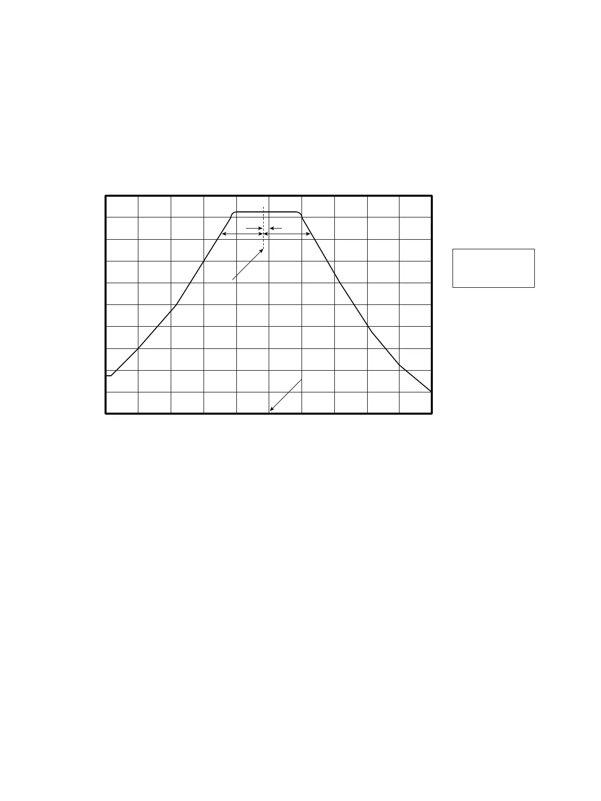
10) Adjust R79 on the 2nd Converter (refer to Fig. 3-2-5) so as to shift the center of filter display about 5 MHz below
the center frequency of the display.
AB
10 dB down point
A=B
5 MHz
The center of filter
Center frequency
(3.2 GHz)
11) Set the spectrum analyzer to :
Center frequency : 20 GHz
12) Set 6769B Signal generator output to :
Frequency : 20 GHz
RF level : -10 dBm
13) Enter Cal menu by pushing “Shift” + “0” keys. Open the second page of Cal menu (press the key “more”), and
enter Maintenance menu with “F6” key.
14) Select key “Mainte RF/Micro Conv” (F2), and press the key “more”.
15) Press the key “Main Swp → off” (F2). At this point YTF filter shape appears on the display of the spectrum
analyzer.
16) Wait 1 minuets.
17) Adjust R70 on the 2nd Converter (refer to Fig. 3-2-5) so as to shift the center of filter display to the center
frequency of the display.
3.2 Troubleshooting