Appendix E: Anybus CompactCom 40 without Housing 112 (114)
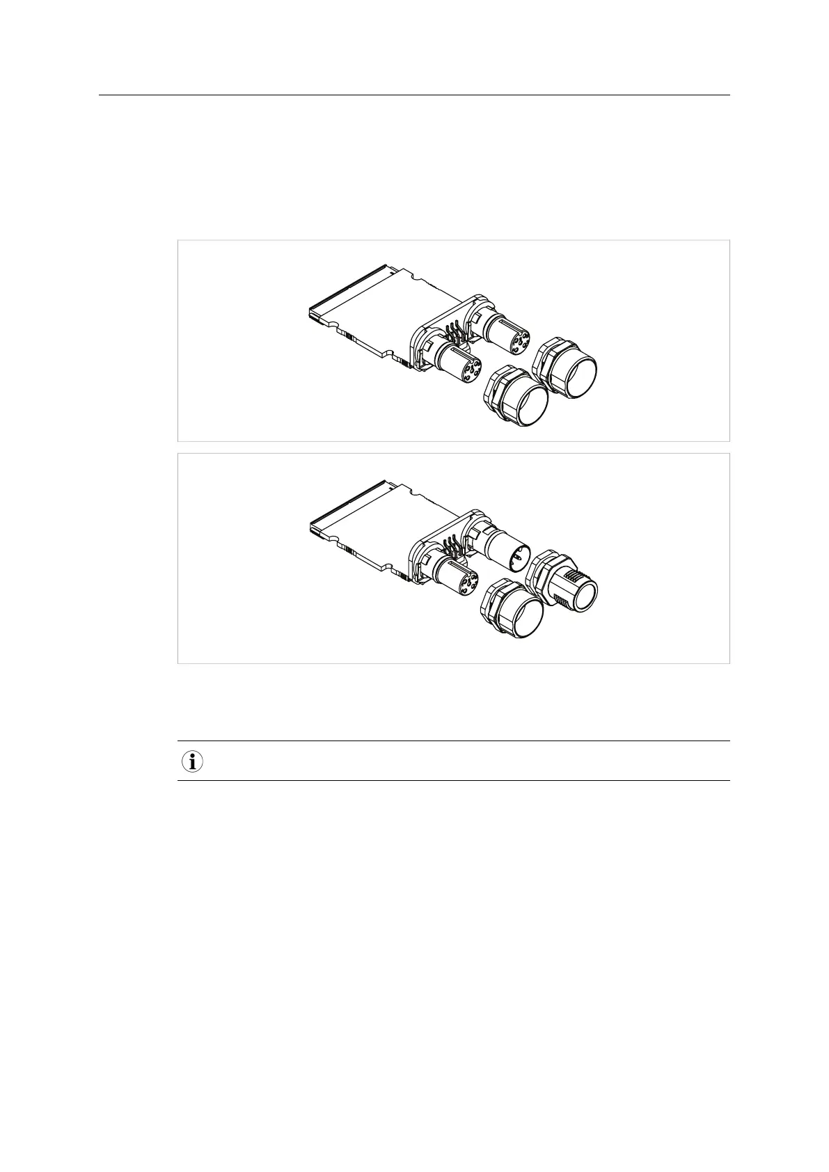
E.8.3 M12 Connector Assembly
The M12 connector parts are not joined on the Anybus CompactCom module at delivery. The
connector has to be tightly mounted on both sides of the front plate if the design is to be rated in
class IP67. The design, preparation and manufacturing of the front plate is not offered by HMS
Industrial Networks AB, but has to be performed by the customer. For dimensions see M12
Connectors, p. 109.
Fig. 72
There are three guides on both the inner and outer parts of the connectors for mechanical
keying, ensuring correct rotation of the outher parts.
Please make sure that the connectors are pushed all the way into these guides at assembly.
Anybus
®
CompactCom
™
M40 Hardware Design Guide HMSI-216-126 EN 2.6