Host Interface 23 (114)
the module using the smaller message format of the Anybus CompactCom 30 series, with a
reduced set of address lines, allowing access to only 256 byte process data, see the Anybus
CompactCom 30 Software Design Guide for more information.
The A0 signal is not needed in 16-bit parallel operating mode, as 16 bits are addressed instead
of 8 bits. If there is need for writing one byte at the time signals WEH and WEL can be used to
enable writing to the high or low byte respectively. If both are enabled both bytes are written.
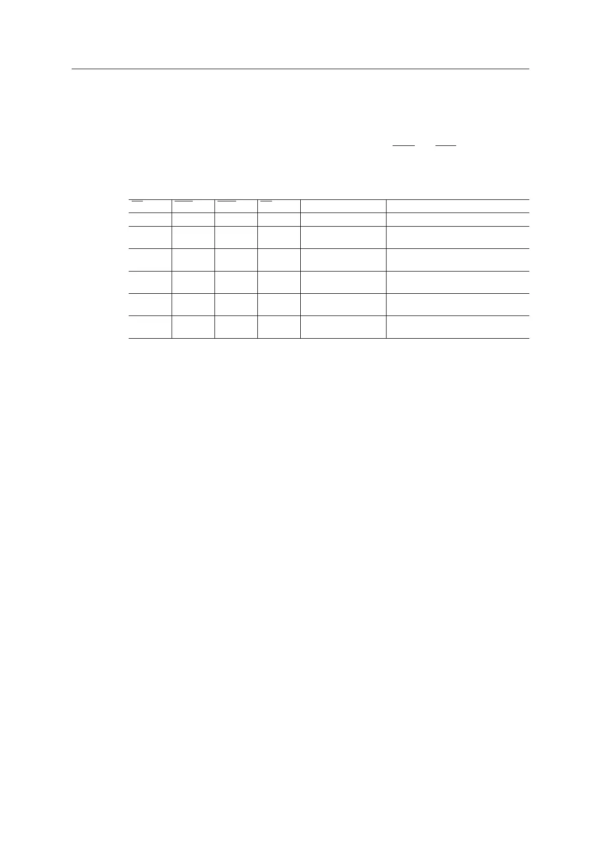
Function Table (CS, WEL, WEH, OE, D[0...15])
CS WEL WEH OE D[0...15] State Comment
HIGH X X X High impedance Module not selected.
LOW LOW HIGH X Data Input (Write) Data on D[0...7] is written to low byte
of location selected by address bus.
LOW HIGH LOW X Data Input (Write) Data on D[8...15] is written to high byte
of location selected by address bus.
LOW LOW LOW X Data Input (Write) Data on D[0 ...15] is written to location
selected by address bus.
LOW HIGH HIGH LOW Data Output (Read) Data from location selected by address
bus is available on D[0...15].
LOW HIGH HIGH HIGH High impedance Module is selected, but D[0...15] is in a
high impedance state.
X = don’t care
LOW = V
IL
HIGH = V
IH
Anybus
®
CompactCom
™
M40 Hardware Design Guide HMSI-216-126 EN 2.6